Why Use a "70.7 Volt" System?
Pat Brown answers this question, Why Use a “70.7 Volt” System? He also clears up some common misconceptions about 70.7V distribution systems.
That’s a good question, and one that causes a lot of confusion among audio practitioners. Here are some common misconceptions about 70.7V distribution systems:
- 1. There is 70.7 volts on the line at all times.
- 2. The 70.7 volts is a “carrier” that the audio is riding on.
- 3. You should be able to hook a voltmeter across the line and measure 70.7 volts during the operation of the sound system.
There are many more. Let’s take a look at the basics of this type of distribution system.
The Constant-Voltage Interface
Part of the confusion is due to the choice of terms used to describe this type of distribution system. This is a constant-voltage distribution system. In a constant-voltage system, the voltage at the output of a component is not affected by the load impedance. So whatever measured voltage exists (i.e.1V, 10V, 70.7V) from any type of signal (sine wave, square wave, pink noise, music – it doesn’t matter) that voltage will be unaffected by changing the load on the amplifier. In other words, it doesn’t matter if the amplifier is driving one loudspeaker or one hundred, the line voltage will be unaffected by the number of loudspeakers on the line. Virtually all interfaces in a sound system are constant-voltage – it is unfortunate that this term has become associated uniquely with a means of distributing signals to zones of loudspeakers.
The Concept
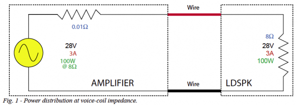
Figure 1 shows how a typical 100 watt amplifier might be interfaced to a loudspeaker. For simplicity, the loudspeaker is simplified to a fixed-value resistance. The very low impedance amplifier output drives the much higher impedance loudspeaker. This is a constant-voltage interface, because the voltage across the amplifier’s output terminals does not depend on whether the loudspeaker is connected or not. The problem with this interconnect method is that due to the very low loop impedance (the amplifier plus the loudspeaker), the circuit is affected by the wire resistance. If the wire must be long, the increased resistance affects the signal transfer between amplifier and loudspeaker. It works just fine for hooking one or two loudspeakers to a single amplifier through a few meters of cable.
A Solution From the Utility Company
The power company has the same problem – the need to provide a waveform to numerous loads (our homes) while reducing the affects of the cable. The method that they use involves taking the power from the generator and ratioing it up to higher voltage and lower current by means of a step-up transformer. Since the current is lower, a smaller wire can be used. The process is reversed at the other end of the line with a step-down transformer. The step-down transformer has another effect – it makes the impedance of that the load presents to the line much higher. This allows many loads to be placed on the line without excessive loading of the source. So, two things have been accomplished though all of this – the wire losses have been reduced and the number of loads that can be driven has been increased.
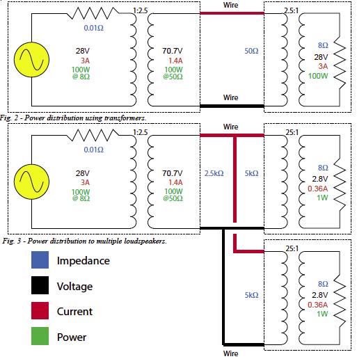
The same method can be used for audio signals. The amplifier output signal is ratioed to higher voltage/ lower current, effectively reducing the required wire gauge (Figure 2). The process is reversed at the loudspeaker end with a step-down transformer. This transformer also makes the loudspeaker’s impedance much higher, allowing multiple loudspeakers to be connected in parallel to a single amplifier (Figure 3).
A Matter of Perspective
Perhaps a better choice of terms would be “high voltage distribution” in lieu of what is happening to the amplifier signal, or “high impedance distribution” in lieu of what is happening to the loudspeaker’s impedance. “Constant-voltage” is correct, but not unique to this interface in the signal chain. 70.7 volts refers to an accepted distribution voltage (determined mainly by code considerations), and describes what would be measured if a sine wave were used as the signal (like the power company). Since we don’t usually feed sine waves to loudspeakers, the measured voltage will vary. The typical value on the line would be 70.7V + 3dB = 100V-peak, less 10dB for the program material crest factor – roughly 30 VRMS or so. Also, if one assumes a sine wave and fixed load values, all of this can be described in terms of power transfer – hence the “watt- age taps” on distribution transformers.
Some “Factoids” About 70.7V Systems:
- 1. The 70.7 volts is the RMS value of the largest sine wave that will “fit” through a 100VDC supply. Typical program material will have a much lower RMS voltage.
- 2. Any voltage could be used. Other “standard” choices include 25V, 100V, and 140V – all for sine waves.
- 3. If the voltage and impedance values are assumed to be fixed (they’re not) then the signal transfer can be described using power rather than voltage or impedance. This makes it easier to keep track of how the amplifier is being loaded, but more confusing in that these power values are only true for the assumed volt- ages and impedances.
- 4. This whole distribution scheme can be described using a power model, voltage model, or impedance model. All three are included in Figure 1.
- 5. The impedance meter is the tool-of-choice for troubleshooting such systems, as it reveals the electrical impedance of the line including the effects of all loudspeakers, transformers, and wire. It effectively shows “what the amplifier is looking at.”
- 6. When the amplifier’s output voltage is ratioed to a higher value, so is the minimum impedance that it can safely drive. For instance, a “28V at 8Ω” amplifier becomes a “70.7V at 50Ω” amplifier with a step-up transformer.
Study the diagram carefully to see how the transformers affect the voltages, currents, impedances and power transfer. pb


