Inside Amplifier Power Ratings – Part 1
by Pat Brown
Inside Amplifier Power Ratings – Part 1, Pat Brown clarifies power ratings.
Could anything be more confusing than a “power rating?” The question “How many watts” can have many answers, depending on whether we are talking about amplifiers or loudspeakers. There are also many variables regarding how power is measured and specified. The numerous variables have rendered “face value” power ratings virtually useless.
Why is “power” so hard to quantify? One reason is because it is time-dependent and constantly changing – much like the “value” of the stock market. We can look at the “highs,” “lows,” or the “average,” and all are different numbers that are useful for different things. Another problem is that we connect power amplifiers to loudspeakers. Given the nature of what each does (and how it does it), the methods used to rate one are inappropriate for the other. A 100-watt amplifier can’t produce 100 watts of power to a loudspeaker unless it plays a very annoying test waveform. Go figure.
Even so, sound system designers must select appropriate amplifiers for the loudspeakers in their projects. The power ratings supplied by amplifier manufacturers must be interpreted and scaled to meet the requirements of the design.
Some of us are old enough to remember the “power rating wars” of the 1970s. Any rating used to sell something is suspect, especially when there are many ways to test it and many more ways to present the results.
But, amplifier power ratings don’t have to be mysterious or confusing. There are some guidelines, assumptions and rules-of-thumb that can simplify the process of amplifier selection without sacrificing accuracy.
A Reference Waveform
The determination of the power of an amplifier can be trivially simple, or very complicated. It depends on the characteristics of the audio waveform and the impedance of the load that it drives. The simplest AC waveform is a sine wave. When applied to a loudspeaker, the sine wave makes it pump in and out like a piston – easy enough to visualize.
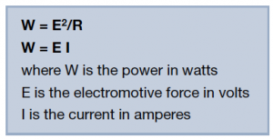
There are several commonly used power equations. Both are pretty simple when used with sine waves driving resistive loads on a test bench.
Power is typically calculated from the effective, or Root-Mean-Square (RMS) value of the audio waveform. Don’t get nervous – this is just a way of averaging the waveform over time to come up with a value that would equal the power (or heat) generated by a constant value of direct current. As such, the RMS value of a waveform is sometimes called its “equivalent DC value” or “heating value.”
This is a very important point. Power generation and dissipation is related to heat and dependent on time. We will revisit that later.
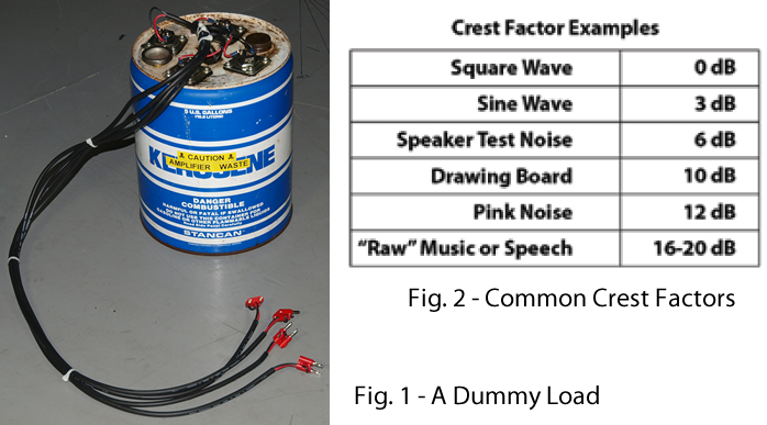
An example will clarify this. Figure 1 shows a dummy load that can be connected to an amplifier. This allows the amplifier to produce power without making sound, which is good for the guy or gal doing the test. The loads are water heater elements submerged in oil. All of the power is converted to heat. The temperature of the load can be monitored with the built-in thermometer.
The AC waveform that has the highest heating value is the square wave, and is equivalent to DC. It shall serve as our reference. I’ll apply 10 volts RMS to the load and allow the temperature to stabilize.
Next, I’ll substitute pink noise for the square wave. The pink noise is pure chaos when compared to a sine or square wave (as are music and speech). How does one give it a value? In order to produce the same load temperature as the square wave, I have to turn the amplifier up by 12 dB. This is called the “crest factor” of the waveform. It is subtracted from the square wave voltage level to find the “effective” or “heating value” of the pink noise. Ten volts RMS of pink noise produces the same power into the load resistor as a 10 VRMS square wave.
Figure 2 is a chart of crest factors commonly encountered in audio work. The EIA standard (now defunct) measures the power from the amplifier using a steady 1 kHz sine wave (3 dB crest factor). While not very realistic with regard to real-world audio applications (unless you are driving a siren), it provides a useful reference wattage that can be de-rated for complicated audio waveforms like music and speech. The EIA standard lives on as CEA-426-B R-2005.
In the Real World
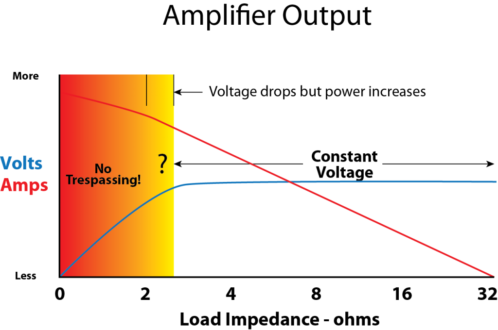
The ideal amplifier is a constant voltage source. This means that the output voltage (which is of course an audio waveform) is not affected by the load impedance. Let’s fix the output voltage to 30 VRMS (about 100 watts continuous into 8 ohms) and consider what happens as the load impedance changes. Please see Figure 3 (Click to enlarge).
Our ideal amplifier is an unlimited source of current. Think “Hoover Dam with Speakons” and you have the right idea. As the load impedance drops, the current increases. As the load impedance increases the current decreases. Each halving of the load impedance doubles the output current and therefore the output power of the amplifier, so long as the voltage remains constant. So, the more paralleled loudspeakers, the more watts.
Real-world amplifiers behave as ideal voltage sources into typical sound reinforcement loudspeakers. You can load them with one or maybe two 8 ohm loudspeakers, and the output voltage is not affected. Like the ideal amplifier, the power doubles as the load impedance is halved.
At some point, this relationship no longer holds and the voltage drops as you daisy-chain more loudspeakers onto the amplifier, even though the output power increases (The yellow region of Figure 3). Below about 3 ohms, this amplifier is no longer a constant voltage source.
Note that since the current is impedance-dependent, a box that can handle a large RMS voltage may not draw much power, if its impedance is high. This can be a useful attribute if I need to parallel multiple line array boxes onto a single amplifier, which is a very common practice. I’ve measured units as high as 60 ohms.
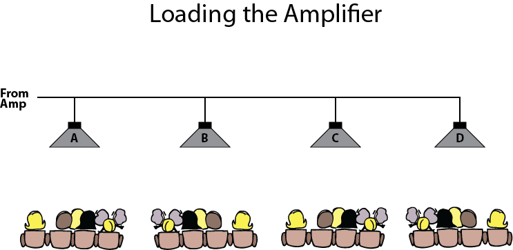
A “power” mindset says “load it down because you get more watts.” But note that even though the output power is increasing in the “yellow zone,” the output voltage is decreasing. If your loudspeakers are covering different zones of the audience, adding additional loads beyond 4 ohms may cause a level drop in the already-playing loudspeakers (Figure 4).
You get the most SPL from Box A if you disconnect the other boxes. In short, the amplifier’s best performance is achieved when it is not overloaded. The impedance of a real-world loudspeaker is higher than its “rated” impedance over most of its bandwidth. While some amplifier’s can handle “2 ohm loads” it would be rare to ever encounter a true 2 ohm load in practice other than with a bank of test resistors.
Besides the voltage drop, there are other reasons why very low impedance loads (i.e. 2 ohms) are problematic. The lower the load impedance, the heavier the required wire gauge. Heavy gauge speaker wire minimizes line loss and preserves the amplifier’s damping factor (significant for subwoofers). Cables for 2 ohm loads must be kept short or they may get ridiculously heavy.
We wouldn’t dream of putting weights in the trunk of our car to make it produce more power. It is equally silly to load down an amplifier to get more watts.
Power Ratings
There are many examples of power ratings outside of audio. Some examples include AC generators, motors, light bulbs, and horses – and many, many others. In every case, the rating given is assumed to be continuous, meaning a sustainable, guaranteed value. When you buy a 5,000-watt generator, you expect to get 5 kW continuous, not short-term peaks of 5 kW. A good horse can generate one horsepower continuous (746 watts) for a period of time long enough to complete a task. This provided a guideline for replacing it with a steam engine.
Audio amplifier power ratings got crazy in the 1970s when some manufacturers began basing their ratings on “peak” or “instantaneous” values rather than “continuous” output. This gave them an advantage in the marketplace, because “more is better.” Right? The Federal Trade Commission stepped in and established a standard to level the playing field. It placed requirements on the bandwidth and distortion level of the audio signal from the amplifier. So did the (now defunct) Electronics Industries Alliance or EIA rating method (now CEA-426-B R-2005).
In short, there are many ways to test both amplifiers and loudspeakers to get power ratings. The oldest and most conservative method for amplifier testing is the use of a continuous sine wave, with the amplifier connected to a resistive load and operated for a specified period of time (”continuous” implies “indefinitely”). I am a big fan of this method, for several reasons.
1) It’s a simple test. There’s no way to fudge it, fool it, fake it or misrepresent it.
2) The rating can be easily verified in the field, with simple instrumentation.
3) I can easily determine the output power with other waveforms (music or
speech) by substituting the crest factor of the program material for that of the sine wave. This always results in less power flow.
4) The distortion of a sine wave is much easier to measure than the distortion of more complicated waveforms, so it is easy to determine when the amplifier is at maximum level.
5) Large power amplifiers can drive distributed loudspeakers systems without the use of a step-up transformer.
These systems base their ratings on the sine wave. If I need “70 volts” or higher to drive such a line, then I need a sine wave rating for the amplifier to know whether it can get there.
As a system designer, I want a simple, no nonsense conservative rating of what the amplifier can do. I can increase the crest factor (de-rate the amplifier) to know the level produced by music or speech.
Now, before the letters to editor start pouring in, I’m smart enough to know that it is unlikely that the amplifier will ever have to pass a full-scale sine wave into a load for an extended period of time unless I intend to use it to drive a shaker table or as a regulated electrical outlet on the test bench (seriously – gota 60 Hz oscillator?).
I’m also smart enough to know that most “embellishments” to this simple rating method are to achieve higher power ratings and an advantage in the marketplace. (The 1970s revisited. Do we really have to go through that again?)
I also understand that some amplifiers can produce more than their continuous sine wave rating if I pulse the test signal. Fine. I’ll take it. It’s only a few dB. In fact, the decibel is the key to understanding and comparing power ratings.
Decibels & Audio Levels
Quick! What is the approximate expected SPL at 4 meters from a loudspeaker with an average sensitivity of 100 dB-SPL (1 W/1m) driven by a 200-watt power amplifier playing pink noise? Got ya, didn’t I? If you had to think about that for very long, or even whip out a calculator, then you’re a victim of a very poor rating system that is used for power amplifiers. The unit is named for Mr. Watt, but I doubt that even he would endorse its use for audio calculations. We’ll solve the problem mentally with simple addition and subtraction, after a little ground work. You will be able to perform complex amplifier calculations in your head, amazing your friends at parties and possibly even improving your love life. I’m an optimist.
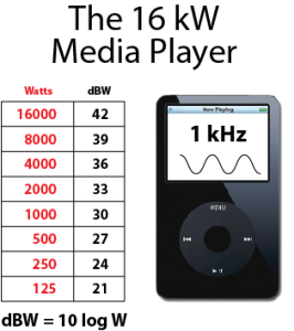
Since the human hearing system perceives power changes proportionally, linear units such as watts and volts are not terribly useful. The Audio Fathers dealt with this dilemma early in the last century by creating the decibel system. The decibel describes the proportional change between two “power-like” quantities. Figure 5 gives some common wattages and their decibel equivalent. The decibel works just like the human hearing system, assessing loudness changes by the proportional change to a reference value.
To compare various power ratings, I’ll pretend that I have a 16,000-watt iPod. Nice! It is connected to a dummy load resistor and is generating a 1 kHz sine wave. Each click of the volume control is 3 dB (true in real life), so the chart has a range of seven “clicks.” Each click generates twice the power, and slightly higher SPL than the previous. This unlikely example serves as a reminder that doubling the power is a meager level increase, even though it may require a lot of watts.
The values on the chart could represent a range of amplifiers from a manufacturer. For you math types, here is the formula:
dBW = 10log(W2/W1)
where W2 is the amplifier’s sine wave rating in watts and W1 is a reference power of 1 watt (Hint: You don’t have to perform the division since we are dividing by 1). The equation simplifies to dBW = 10 log W. Each power level is how the amplifier would compare in level to a one watt reference.
If you just memorize the chart, you won’t even need a calculator. One nice thing about power amplifier calculations is that you only need to get close.
These are typically sine wave ratings, but can be scaled to “pink noise” ratings (which are more like music) by simply subtracting 10 to account for the higher crest factor of pink noise as compared to a sine wave. (The sine wave has a 3 dB crest factor, and pink noise is about 12 dB, or “9 dB higher” than the sine wave. 10 dB is close enough and is easy to work with).
The resultant level in dBW can be added to the loudspeaker’s average sensitivity to determine the SPL at 1 meter. The 1-meter SPL can be extrapolated to a greater distance by simply halving it for every doubling of distance, which is the inverse-square law rate of level change. How about an example?
Loudspeaker: KillSound 5000
Sensitivity: 100 dB-SPL Average (1 W/ 1 m)
Amplifier: Kilo-Blaster 1000
Power Rating: 1000 W continuous at 1 kHz into 8 ohms
1. dBW = 10 log 1000 = 30 dBW
2. Pink Noise Power = 30 dBW – 10 dB = 20 dBW
3. Loudspeaker SPL: 100 dBSPL + 20 dB = 120 dB-SPL at 1 meter
4. Level at 4 m: 120 dB-SPL – 6 – 6 = 108 dB-SPL
So, practice subtracting 10 and subtracting 6 (repeatedly) from your starting values and you can quickly estimate the SPL from any loudspeaker with any amplifier at any distance.
Meaningful Representation
The decibel has done exactly what it was designed to do – make audio simpler, more intuitive, and most of all, provide a meaningful representation of the level change that results from changing the power. Amplifiers should be rated in dBW, not watts, for these reasons.
Now, I’m not naive enough to think that amplifier manufacturers will actually publish dBW instead of watts. A large percentage of their customers would not understand their specs, and their tech support phone calls would go through the roof (and maybe their sales through the floor!). You will have to make the conversion yourself with the chart. You will have the typical amplifier sizes memorized in no time.
In light of these facts, can an amplifier have a higher power rating than the outlet from which it is powered, as some modern amplifiers claim to? Are these legitimate ratings or is it the 1970s revisited?
In the second part of this series I’ll look at how that works, and provide some perspective on the “kilo-amp” wars. pb

