Tuning Subwoofers with No Cables Attached – Evaluating One Wireless Alternative
by Robert Bernecker, Pres. SEFI Consulting, Inc.
The article evaluates One Wireless Alternative to Tuning Subwoofers with No Cables
In the process of commissioning and tuning high performance audio systems, professional audio practitioners often need to measure the response of the subwoofer(s) in these systems. Such measurements are fraught with any number of difficulties, including such things as room modes, interference between spaced devices, reflections from room surfaces, and varying distances from disparate sources. Unless one is employing Don Keele’s well-known extreme close-mic solution (see item 6 at http://www.xlrtechs.com/dbkeele.com/papers.htm), these difficulties conspire together to present the practitioner with the dilemma that there is no single microphone position that is “correct” for the needed tuning measurements, nor do multiple microphone averages adequately deal with these barriers to quality measurements. One solution developed by the author and used successfully for well over 10 years is a method of moving about the room slowly with an analyzer set to “accumulate” or “infinite average,” thereby gathering what the author refers to as an in situ low frequency power response measurement.
In the past, this was often accomplished with an Audio Toolbox instrument, but this instrument has since been retired. The concurrent needs of accurate measurements at low frequencies, high resolution of 1/48 octave or greater, a screen large enough on which to actually see and interpret detail (as opposed to a 4 inch cell phone screen), and the ability to easily overlay multiple stored measurements have pushed this measurement back into the realm of the usual on-site laptop computer software tools. For example, SysTune by AFMG includes an easily implemented “ infinite” setting for the number of averages included within a measurement, and this has become a preferred method for making this sort of low frequency measurement.
If one is to move about the space in the process of gathering this measurement, a long microphone cable can become easily tangled, knotted, or hung—this even more so as the process is repeated successively during the tuning process. As such, a wireless measurement solution would be quite desirable for this application. However, it is vital to verify that any wireless system is a transparent part of the measurement chain—or one must otherwise know and compensate for the limitations and/or distortions of the wireless system employed.
For a number of years, the gold standard for wireless measurement systems has been the Lectrosonics TM400. However, this excellent system has a roll-off in the low frequency region that would seem to render it less than optimum for low frequency measurements, even when the lowest HPF setting (35 Hz) is selected.
The manufacturer’s specification (http://www.lectrosonics.com/US/phocadownload/tm400td.pdf) shows that the response of the TM400 begins to roll off sharply at 40 Hz, and it is down 6 to 10 dB at 30Hzand 12 dB or more at 25 Hz. This roll-off, therefore, lies squarely within the region of interest when tuning subwoofers.
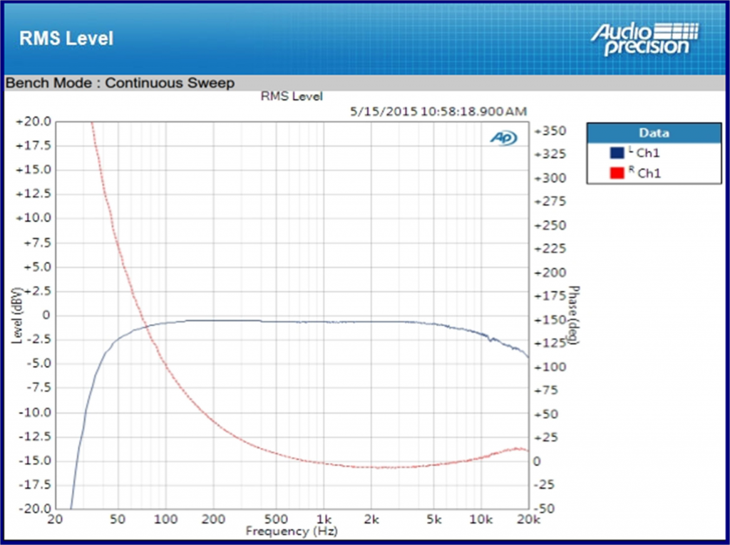
An actual loopback transfer function measurement for the TM400 wireless system is shown in Figure 1:
The measurement shown in Figure 1 confirms the low frequency roll-off in the TM400 system. Additionally, the phase response measured here would be a significant and problematic factor for typical tuning tasks such as aligning a mid to low or low to sub crossover in the range below 500 Hz. The phase response of this wireless measurement system below 1kHz would also obviously come into play in a detrimental manner if one were to attempt to use a measurement from this system to develop a phase-correcting FIR filter.
As such, other wireless systems were considered that might be more suitable for measurements in the lower frequency ranges. After surveying the current marketplace, it appeared that the Line 6 XD-V75 digital wireless system could be a possible alternative for a wireless system capable of measuring well into the subwoofer frequency range. Doug Fowler has previously posted several articles about his use of the Line 6 XD-V70 system for wireless measurements (http:// line6.com/news/general/1330/ ). The newest Line 6 XD-V75 system is a digital system operating in the 2.4 GHz range, and it is a candidate for measurement use because it does not employ a compander circuit.
This system by Line 6 is certainly a lower cost alternative to the TM400 system, but a major obstacle is the lack of phantom power needed for the measurement microphone. As one prominent example, the Earthworks M30 is a popular measurement microphone that is well-known for its relatively high current requirement from phantom power—approaching the 10mA limit of the phantom power specification. Many battery operated phantom power supplies are not capable of delivering either this amount of current or the full 48 V (before the expected IR drop). Moreover, many battery operated supplies do not have a form factor conducive to use in a field measurement system.
As a potential phantom power supply, the AKG B48L seemed to offer the desired combination of form factor and performance, since it is designed to mount directly onto a microphone and is rated to deliver the full 48V and 10 mA of the P48 specification. The B48L manufacturer’s specifications are available at http://www.akg.com/pro/p/b48l. A simplified schematic is also included in the user’s guide. An AKG B48L was obtained, and it was carefully measured to verify its performance, particularly when driving an Earthworks M30 measurement microphone. This choice was based on the premise the B48L will likely work well with most other commonly used measurement microphones if it is able to satisfactorily drive a M30.
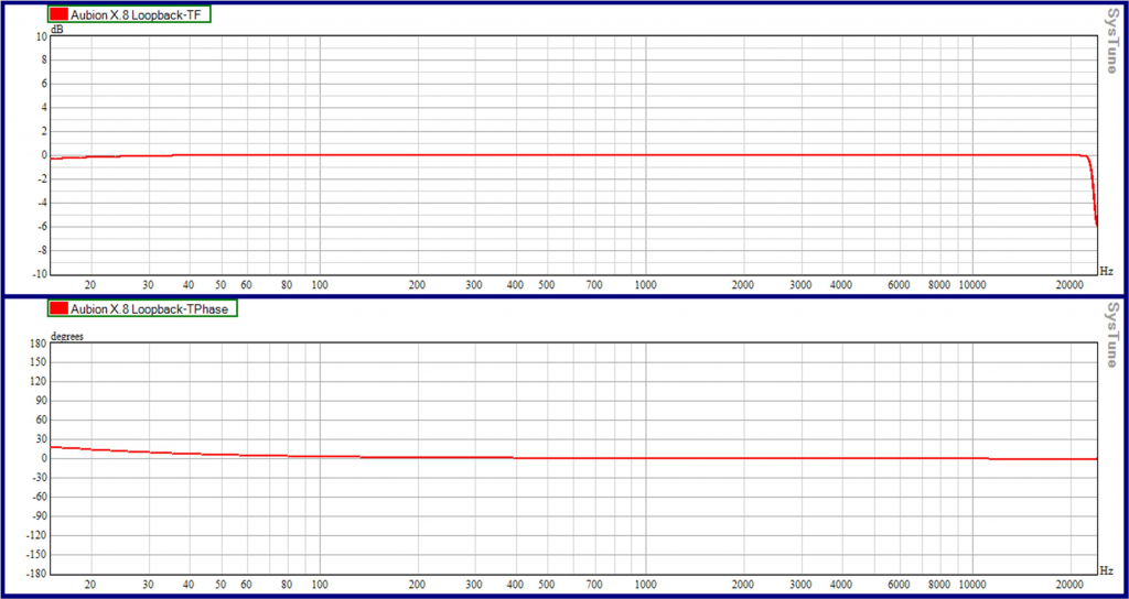
Before testing the combination of the Line 6 XD-V75 wireless system and the AKG phantom power supply on a M30 microphone, each part of the measurement chain was initially measured individually. For this testing, AFMG’s SysTune software and the associated Aubion X.8 hardware measurement interface were used. To establish a baseline and identify any anomalies attributable to the measurement system itself, the Aubion X.8 was first looped back into itself (an external direct cable connection from output to input). Not surprisingly, the X.8 performs quite well, as seen in Figure 2 below. (Figures 2, 3, and 4 all show results of measurements made with an FFT size of 65,536 samples, 48 kHz sampling rate, and 1/48 octave smoothing.)
In this hardwire loopback, the magnitude response of the Aubion X.8 interface is flat to within a small fraction of a decibel from 20 Hz up to the Nyquist frequency of 24 kHz, and the phase response displayed in SysTune is flat and only a few degrees out at 20 Hz, presumably due to the inherent bandpass nature of the system.
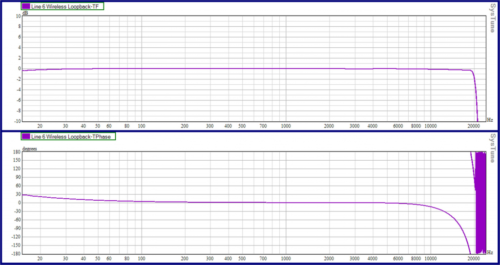
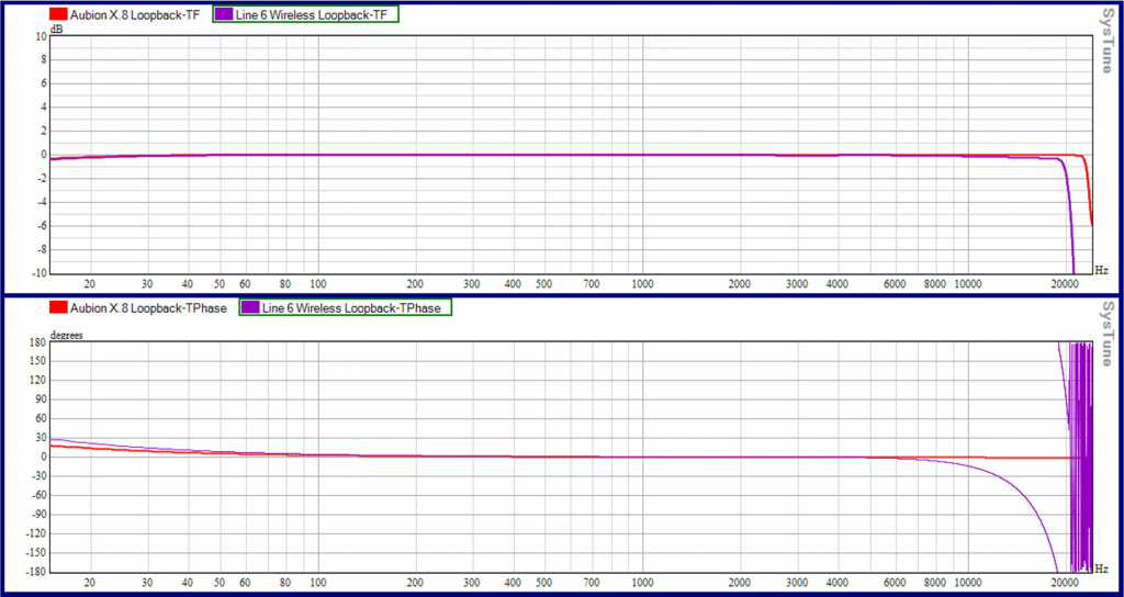
Next, the Line 6 wireless system was loopback tested by feeding the output of the Aubion X.8 directly into the input of the TBP12 wireless beltpack and connecting the output of the XD-V75 wireless receiver to the input of the Aubion interface. These simple measurements are presented below in Figure 3. The measurements of the Line 6 and the X.8 are overlaid in Figure 4 to allow for an easy visual comparison.
As seen in Figures 3 and 4 above, the Line 6 wireless system rolls off sharply right at 20 kHz. Moreover, the phase shift associated with this apparent LPF extends back to around 8 kHz. For many measurement tasks, this LPF would obviously be a non-issue, for others it could be a consideration (e.g., when employing Heyser’s wisdom on determining correct receive delay). On the low frequency end of things, it would appear that the Line 6 wireless system performs admirably, with magnitude and phase essentially flat to below 20 Hz (note the minor LF phase difference in the X.8 itself is of course also included within the Line 6 measurement).
The measured impulse responses for the X.8 loopback and the Line 6 wireless loopback are shown in Figure 5. The X.8 impulse response is Dirac-like, with the large spike of energy being only 1 sample (.02 ms) wide and dwarfing the minor bandpass ripples. Although the impulse is shown shifted left here, the measured latency for the Line 6 wireless system was 2.9 ms.
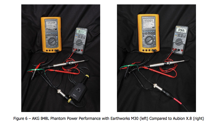
The next step was to verify the performance of the AKG B48L, more specifically its ability to deliver the current requirement of the Earthworks M30—a microphone known for its propensity to push phantom power supplies to their limits. The AKG B48L was first measured with a Fluke 867B to output 48.4 VDC into an open circuit (pins 2 to 1 or 3 to 1). Breakout jigs were then inserted between the M30 and the B48L, and the voltage and current delivered to the M30 were measured. As a comparative reference, the M30 was subsequently connected to the Aubion X.8, and the voltage and current delivered to the M30 by the Aubion’s phantom power were also measured. Both of these measurements are shown below (Figure 6).
The measurements in Figure 6 were done for each leg (pins 2 & 3) separately in order to verify the expected symmetry. As shown in the photos above, the B48L provided 15.3 VDC across pins 1 & 2 to the Earthworks M30, and the M30 was drawing 7.11 mA of current (again, this is per leg; 14.22 mA was the total current). The Aubion X.8 provided 47.4 VDC open circuit and 15.0 V across pins 1 & 2 of the M30, and the M30 was drawing 4.66 mA of current (per leg, 9.25 mA total). As an example of a battery operated phantom power supply that has difficulty with the M30, the well-regarded Whirlwind MD-1 was measured to provide 17.4 VDC open circuit and only 11.4 V into the M30 with a total combined current of only 1.8 mA (not pictured).
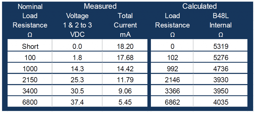
The difference in current between the B48L and the Aubion X.8 with a nearly identical voltage drop suggested a significant difference exists in the current-limiting resistors within the respective devices. Additionally, the 14.22mA of current seen when the B48L was powering the M30 seemed high, so further measurements were made. The B48L was measured to deliver 18.2mA into a direct short (pins 2 & 3 shorted to pin 1 through the Fluke 87III ammeter). This again seemed high, calling into the question whether 6.8 kΩ resistors were actually used as current-limiting resistors inside the B48L as the user guide indicates—since 48 V across3.4 kΩ would be only 14.12mA.
As such, a series of measurements was made (Figure 7). For each measurement, it was also calculated what the internal current-limiting resistors for the B48L would be with the [probably incorrect] assumption that the 48.4 VDC from its internal DC to DC converter was stiff enough to source at least 18.2 mA without sagging. Without a full schematic or tearing down the device, one can only make speculations. However, the measurements in the table would tend to suggest that the DC to DC converter sags below 48 VDC until the load approaches1500 ohms or greater, and the indication is that the internal resistors are right around 4 kΩ. Intuitively, if the internal resistors are indeed 6.8 kΩ as shown in the AKG user manual, then the measured voltage when driving a load of 3.4 kΩ should be 24 V (and 7.1 mA) and not 31 V.
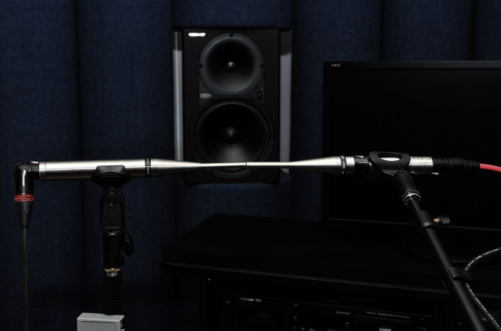
Notwithstanding the question of the current – limiting resistors, it did appear that the B48L was up to the task of providing adequate phantom power for the M30 to operate normally. The next step was to verify this conclusion with actual measurements of the microphone’s performance while operating on the AKG B48L. To facilitate this verification, an Earthworks M30 was set up to compare to an Earthworks M550 which is used as a “never-leave-the-office” reference microphone at SEFI Consulting. By placing the two microphones nose to nose, it is possible to make a good comparison of the two microphones’ responses. The two mics were placed in line with the source (the speaker in the background), leaving approximately the thickness of a business card between the faces of the microphones (Figure 8).
For all of the measurements presented herein, the M550 was set up as the reference input within SysTune, while the M30 was designated as the measurement input. Initially, the response of the M30 was referenced to the response of the M550 with both of these microphones plugged directly into the Aubion X.8 and operating from the X.8’s phantom power (Figure 9, blue). This measurement was then compared to the M30 when operating on the AKG B48L phantom power supply (Figure 9, orange). This established a baseline for comparisons to the response of the M30 when used with the Line 6 wireless link and powered by the B48L.
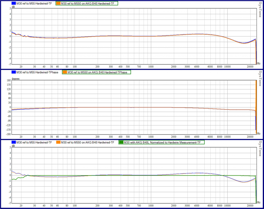
Figure 9 – M30 Referenced to M550, Phantom Powered by X.8 9blue and by B48L (orange);
Difference Between Two Phantom Power Options (green, lower chart)
All Measurements 65,536 sample FFT, 1/48 Octave Smoothing
These plots verify that there is virtually no difference between the performance of the Earthworks M30 when powered by the Aubion X.8 and when powered by the AKG B48L. To be clear, the Line 6 wireless was not in the chain for the tests shown in Figure 9. By using SysTune’s “normalize” feature, it is possible to display the deviation of the response of the M30 while operating on phantom power provided by the AKG B48L from the response of the M30 when operating on phantom power provided by the Aubion X.8 (with a direct cable connection to the X.8 for the signal in both cases). That normalized trace is shown as the green trace in the bottom graph of Figure 9. This is essentially a flat line from 20 Hz to above 20 kHz, so it seems reasonable to conclude that the Earthworks M30 operates nearly identically with the phantom power of the B48L as with the X.8’s, with the caveat that no attempt was made to measure or verify maximum SPL capabilities.
It should also be noted that the 8” speaker used as a signal source for these measurements was not delivering a lot of energy below 20 Hz, so the measurement was “wandering around” a bit at 20 Hz and below. Based on observation during testing, it would be expected that even the small variations below 20 Hz would flatten out if more energy in the 20Hz range had actually been present.
Having verified the performance of the Earthworks M30 while operating on the AKG B48L, the Line 6 wireless system was then introduced into the measurement chain. By leaving the two microphones on stationary stands in the same positions and only changing the cable from the output side of the B48L, it was possible to introduce the Line 6 wireless into the measurement without physically disturbing the microphones. The results of this measurement are seen below in Figure 10.
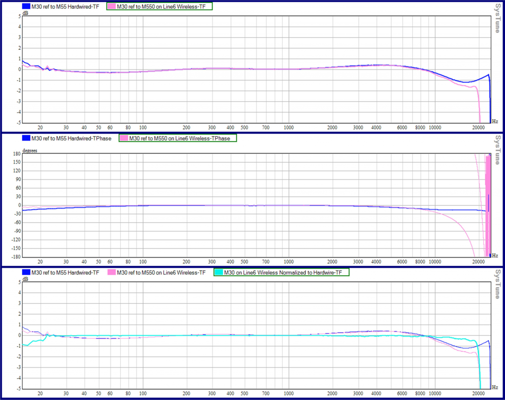
Figure 10 – M30 referenced to M550, Direct to X.8 (blue) vs Line 6 Wireless and B48L Combination (pink);
Difference Between Hardwire and Wireless System (aqua, lower chart)
All measurements 65,536 sample FFT, 1/48 Octave Smoothing
In this measurement (Figure 10), the same difference between the two Earthworks microphones is seen, and the wireless trace (pink) does in fact reflect the effects that would be expected from the transfer function initially measured for the Line 6 wireless system in the loopback test (Figure 3). The low frequency response of the Line 6 system is spot-on, and the effects of the previously observed LPF around 20 kHz on the Line 6 wireless show up from about 10 kHz and up on the magnitude and phase traces. The normalized trace (the difference between the hardwired and the wireless measurement) is shown in aqua on the bottom graph. The trace is flat from about 20 Hz up to around 10 kHz, where it begins to roll off slightly but is only about .5 dB down around 18 kHz.
Based on these measurements, it seems a reasonable conclusion that the Line 6 system is capable of resolution and accuracy suitable for many acoustic measurements typically made in the field. What are not verified here, however, are the effective wireless range of the system and the system’s immunity to RF interference in environments where the 2.4 GHz band may be crowded. Nonetheless, it is fair to say that initial results from actually using this system in the field have been quite favorable.
Figure 11 below is a field measurement which employed the Line 6 system to gather an in situ low frequency power response type of measurement. The measurement shown is again a 65,536 sample FFT, with 1/48 octave smoothing, as it was captured midway in the tuning process—after some initial adjustments but before the final tuning. The red and blue traces below each represent a wireless measurement gathered by moving across the listening area in a particular pattern over a period of time of about 4 to 5 minutes each. A measurement captured from a wired microphone at a single stationary location is also shown overlaid in light blue, and the benefits of the power response measurement are clearly distinguishable. Other single stationary microphone locations would obviously have resulted in completely different captured responses for each such location.
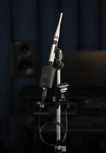
Because the AKG B48L mounts directly on the microphone, it is possible to develop reasonably compact and transportable solutions, albeit not as nicely self-contained as the TM400 system. A Shure WA310 cable was used between the XLR-M output of the B48L and the TA4M input of the Line 6 beltpack (with a simple wiring modification on the XLR side of the cable, moving the shield of the unbalanced cable from pin 1 to pin 3). Figure 12 illustrates one possible solution for using the Line 6 / AKG combination with a microphone mounted on a light stand.
For gathering in situ low frequency power response type measurements, the usage would be hand held instead of stand mounted, of course, and the beltpack could be either clipped to the belt or simply carried.
In summary, the Line 6 XD-V75 and AKG B48L combination is a viable, relatively low-cost candidate for wireless measurements, including measurements of the lowest operating range of subwoofers. This article is in no way intended to be an exhaustive comparison of all wireless measurement options or of all low frequency measurement techniques. Rather, it is hoped that the information herein is helpful as a starting point for audio professionals seeking and researching good solutions for both measurement toolboxes and tuning techniques. RB

