Frequency Response Matching – Should This be Part of the System Tuning Process?
by Pat Brown
“Frequency response matching” is a popular endeavor in both professional and consumer audio systems. Should this be part of the system tuning process?
A logical use of audio filters is to attempt to “match” the frequency response of a microphone, loudspeaker, amplifier, or room to that of another. The logic behind this is the belief that if two components have the same frequency response “curve” they will sound the same. There are even software plugins that can “curve match” automatically and in real-time.
Can this really work? Let’s look at when it can, and when it can’t.
The Frequency Response
Figure 1 shows a plot of level vs. frequency, the so-called “frequency response.” This plot can be produced for any audio component, including mixers, amplifiers, and loudspeakers. It is found on many spec sheets.
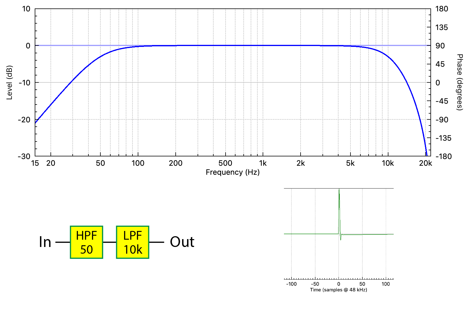
Figure 1 – The frequency response magnitude of a band-pass filter. Also shown are the signal chain and its response to an impulse (IR). The IR is the time domain response of the BPF. All responses and plots were produced by FIR Designer M (Eclipse Audio).
The response shown is that of a band-pass filter (BPF). It consists of a high-pass filter (HPF) at low frequency (50 Hz), and a low-pass filter (LPF) at high frequency (10 kHz). Since audio components cannot typically pass frequencies down to DC, nor up to infinity, all audio components are band-pass filters in addition to whatever else they do to the signal.
More correctly the plot in Figure 1 is the frequency response magnitude. It shows the relative levels of the frequencies that pass through the signal chain. This is only part of the story. There is a second component – the frequency response phase. The phase plot reveals synchronization and timing information about the frequency response components. Collectively, the magnitude and phase response is called the transfer function (TF) (Figure 2).
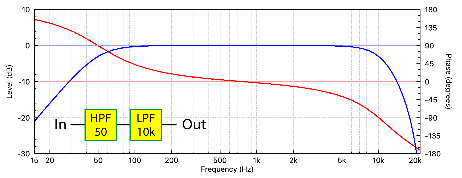
Figure 2 – The transfer function of the band-pass filter. The impulse response (time domain) or transfer function (frequency domain) present the same information in a different way.
Phase Shift
Why would the frequencies get out-of-sync? The very fact that there is a high pass and low pass behavior means that filtering has taken place. In the analog world, filters are constructed by reactive components such as capacitors and inductors. These devices produce phase shift for the frequencies that pass through them, changing both the level and phase relationship between the filter’s input and output frequencies. Phase shift is an unavoidable byproduct of filtering audio with reactive components.
Phase shift also occurs when reactive components are emulated with active circuitry and some types of digital signal processing (DSP).
Minimum Phase
Not only is phase shift unavoidable with analog circuitry, but it can be completely predictable. If all one knew was the frequency response magnitude of a component, the minimum amount of phase shift that had to occur can be calculated from the magnitude response. This is logically called the minimum phase response. Some measurement programs can calculate the minimum phase response from the magnitude response using a mathematical Hilbert transform (Figure 3).
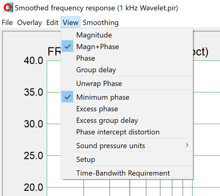
Figure 3 – ARTA™ is one of several measurement programs that can calculate the minimum phase response from the magnitude response.
The phase plot is telling us that phase shift is occurring in the frequency ranges acted on by the HPF and LPF. The phase shift is zero at the center frequency (about 1 kHz) meaning that the filters are having a negligible effect in that frequency region.
Here’s where it gets interesting. A given frequency response magnitude can have an infinite number of phase responses, but it can only have one minimum phase response – the one calculated using the Hilbert Transform. I’ll come back to that.
Most audio components, such as mixers and amplifiers, are minimum phase. In a minimum phase system, the magnitude and phase response are interlocked. You can’t change one without changing the other, and one predicts the other.
When this is not true, the response is non-minimum phase. What could make that happen?
Non-Minimum Phase
Here’s an example. An all-pass filter (APF) is a filter that produces phase shift without changing the magnitude response. In the old days these were often produced by summing the output of a matched high-pass and low-pass filter (Figure 4). Note that the summed frequency response magnitude is identical to that shown in Figure 2. The Hilbert transform of the summed magnitude response will produce the phase response shown in Figure 2. But unfortunately, it will be wrong.
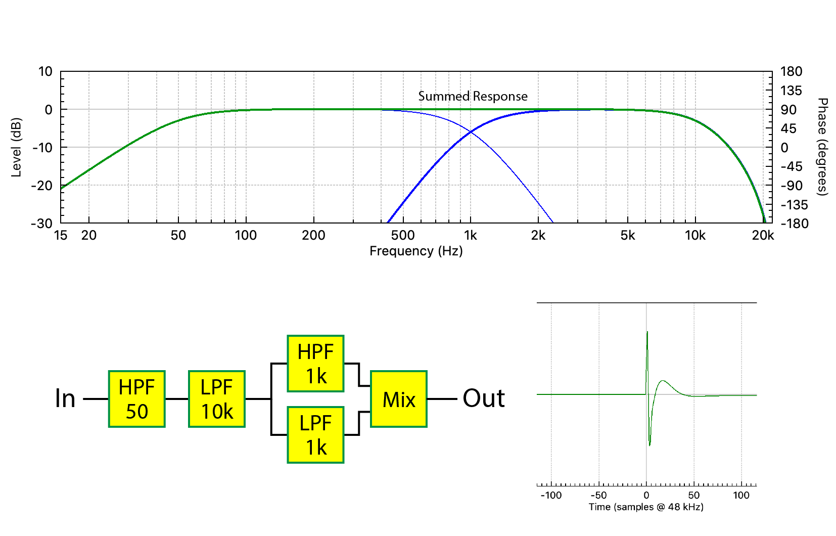
Figure 4 – The summed HPF and LPF form an all-pass filter (APF).
Figure 5 shows the TF. Note the increased phase shift centered at 1 kHz caused by the summed HPF and LPF. This is an example of a response that is non-minimum phase.

Figure 5 – The APF produces additional phase shift in the transfer function. Compare to Figure 2.
These days we don’t have to create APFs manually. Many signal processors include them as filter blocks, as they are sometimes used to address synchronization issues in loudspeakers. I’ll replace the summed HPF and LPF with an APF (Figure 6).

Figure 6 – The summed HPF and LPF has been replaced with an APF. The TF is identical to that shown in Figure 5.
If I cascade additional APFs there is more phase shift, yet the frequency response magnitude remains unchanged (Figure 7). In fact, there are an infinite number of combinations of APFs that I could create, yet no combination would change the frequency response magnitude.
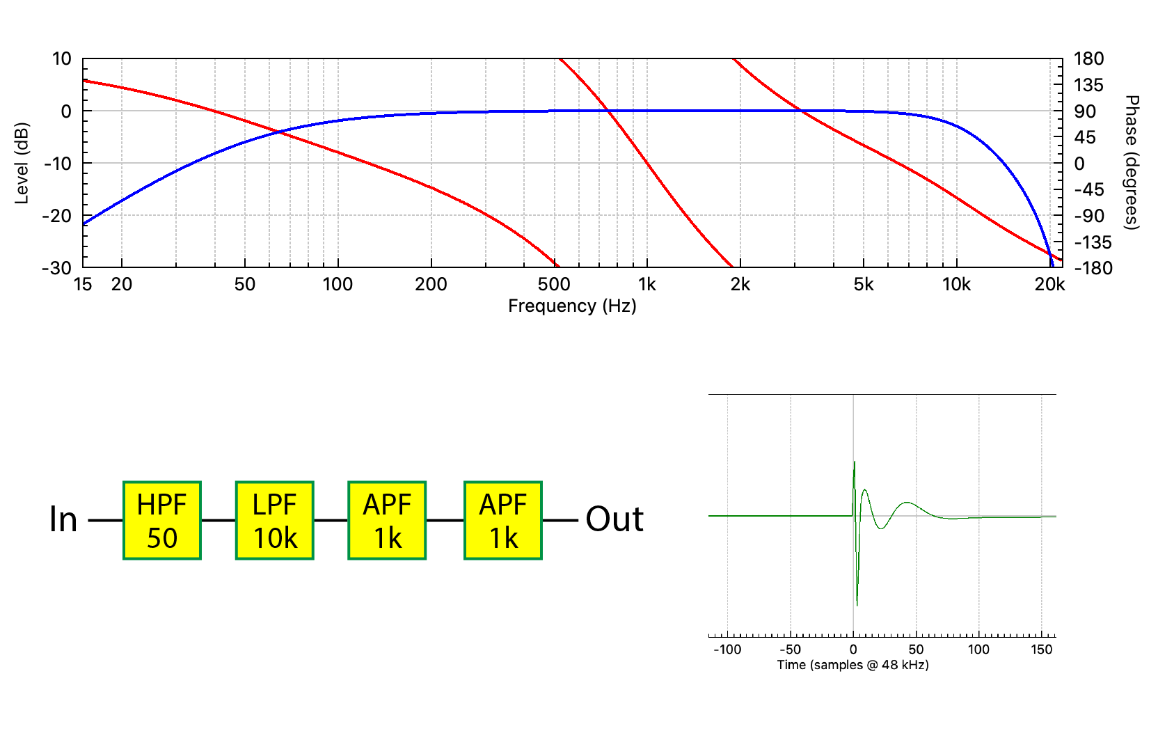
Figure 7 – Additional APFs produce more phase shift. Note the effect of this phase shift on the IR. Even though its shape is altered, there is no effect on the frequency response magnitude.
I’ll repeat the truth statement from earlier in the article.
A given frequency response magnitude can have an infinite number of phase responses, but it can only have one minimum phase response.
Let’s add a term. Comparing Figures 2 and 7, Figure 7 contains a lot more phase shift, caused by the APFs. This additional phase shift is called the excess phase. The excess phase is the difference between the actual phase response and the minimum phase response. If we remove the excess phase (bypass the APFs) from the plot in Figure 7, we’ll be back to the minimum phase response.
What’s In a Phase Plot?
I’ll complicate things further by adding a delay block into the chain, wreaking havoc on the phase plot (Figure 8). Note the 50 sample (1 ms) displacement of the IR. A phase plot is easy to measure, but what does it mean?
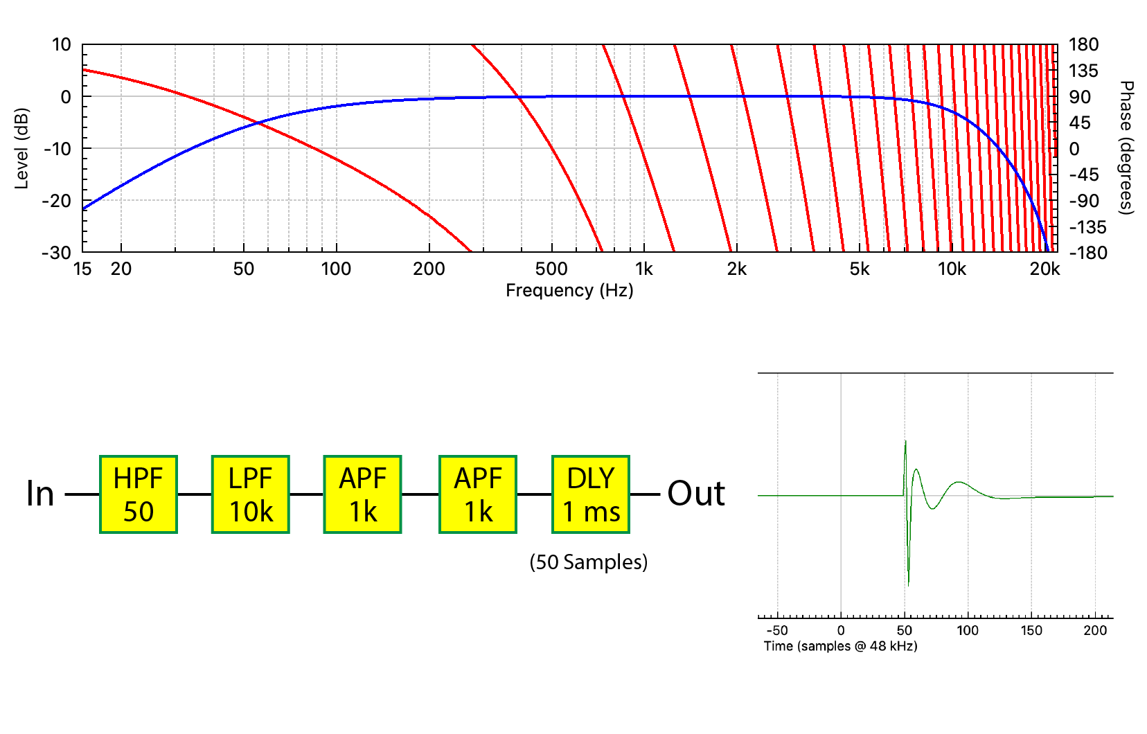
Figure 8 – A delay block has been added to the signal chain. Note its effect on the phase plot and the IR, yet the frequency response magnitude remains unchanged.
A a phase plot can contain at least three types of information – phase shift, polarity, and delay. It’s tempting to refer to all as “phase” since they influence the phase plot, but they are distinctly different. For this reason, phase plots often appear non-sensical at first glance. It’s like looking into a pot of soup after the ingredients have been mixed – it’s hard to figure out what’s in there. Let’s examine the ingredients that influence a phase plot.
1. The phase shift produced by filtering the audio. This includes the excess phase if present.
2. The polarity (sign) of the audio waveform. Changing it inverts the IR (time domain) and displaces the phase plot by 180 deg at all frequencies. It does NOT change the waveform shape, which is why it is not phase shift.
3. Delay. The delay has a similar signature as phase shift. It produces a slope increase. The delay must be removed to observe the phase response of the component (Item 1). This is easily accomplished by many modern measurement systems, either manually or automatically. Delay does not change the shape of the IR.
Here’s the important point. Even with this filtering and delay, the magnitude response remains unchanged! And now our mantra again…
A given frequency response magnitude can have an infinite number of phase responses, but it can only have one minimum phase response.
By extension we can draw an important conclusion: There are an infinite number of impulse responses that can produce the same frequency response magnitude.
For those using measurement software, a useful exercise is to work backwards through my examples. Starting with Figure 8, subtracting the delay should yield Figure 7. Comparing this to the calculate minimum phase response will yield the excess phase. From this one can deduce the presence of one or more APFs. If you are testing a full-range loudspeaker, the excess phase is likely caused by a crossover network. Phase plots must be sorted out using the process of elimination.
Frequency Response Matching
Now we have enough tools on the table to return to the original topic.
Frequency response matching can yield beneficial results for components that are minimum phase. Changes to the magnitude response (using minimum phase filters) will also change the phase response. In fact, meaningful comparisons between mixers, amplifiers, and loudspeakers should probably begin with matching the frequency response magnitudes of the devices using minimum phase filters.
As I have shown, there can be all sorts of stuff happening to the phase response that doesn’t show up in the magnitude response. Phase shift can dramatically alter the shape of a waveform passing through a component and therefore the sound heard by the listener. Since a given magnitude response can have an infinite number of phase responses, there are (in theory) an infinite number of completely different “sounding” audio components that can have the same frequency response magnitude. These can include microphones, mixers, amplifiers, loudspeakers, and especially rooms. Frequency response matching may make two components sound more similar, but it can only make their responses the same if they are minimum phase.
The Spatial Component
So far, I have only used point-to-point examples, such as the input and output of an amplifier. In the world of acoustics there is also a spatial component. Even if one could match the TF (or IR) of two microphones or loudspeakers at a single point in space (e.g., on-axis), there are an infinite number of possible measurement points around the device. This makes it impossible to perfectly match two acoustical components using signal processing alone.

Figure 9 – The major filter blocks found in DSPs. The symbol for a filter is its frequency response magnitude.
Some Conclusions
The frequency response magnitude paints a broad-brush stroke regarding the response of a component. The details can be found in the phase response. These include phase shift, polarity, and delay. A complete description of a device’s response is found in the impulse response (time domain) or transfer function (frequency domain). There is an additional spatial component for devices with an acoustic input (microphone) or output (loudspeaker). Unfortunately, we can’t use different EQ curves for different listeners covered by the same loudspeaker. Rooms are worse yet, and present complexity that belies correction with signal processing alone.
The frequency response magnitude presents only a part of a device’s frequency response. The frequency response phase completes the picture. Together they form the transfer function (TF). Applying an inverse FFT (iFFT) to the TF yields the impulse response (IR) in the time domain. Digital filters are classified by the length of their impulse response, which can be finite (FIR) or infinite (IIR). Each has strengths and weaknesses, and most DSPs offer both (Figure 9). pb
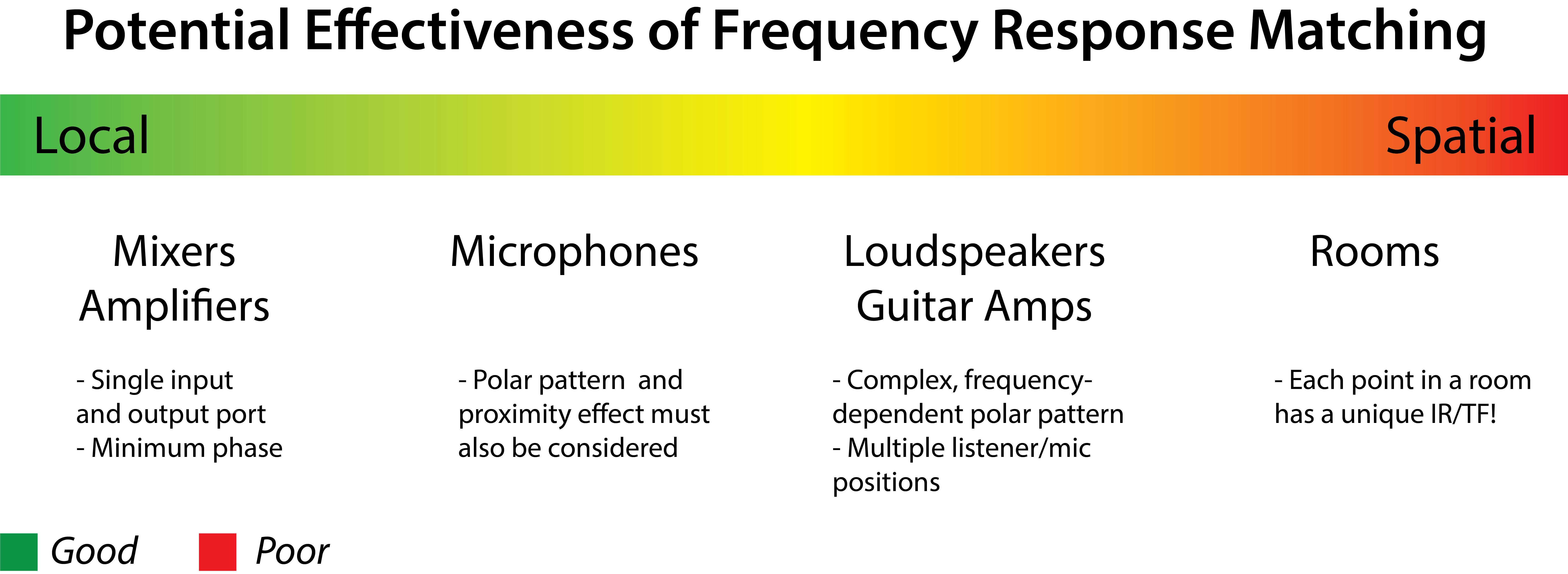
Figure 10 – Effectiveness of frequency response matching (my opinion)
