Take a walk in Loudspeaker Park with me – Part 4
A bunch of kids are running though Loudspeaker Park from the electric to the acoustic end. Near the end they come across a huge piece of sewer pipe lying off to one side. Some of the kids go through the pipe, others go by and directly out the gate. They all meet up at the acoustic exit—but the kids who went through the pipe arrive a bit later.
I am convinced that ported (or vented) so-called ‘’bass reflex’ designs were inspired by the theory of double-tuned circuits as formulated by Heaviside. He observed that two inductors with mutual coupling and with the same tuned frequency in both primary and secondary behave rather strangely (in an extremely useful way) when the mutual coupling is changed. See the good old Radiotron Designers Handbook for more on double-tuned circuits, specifically these pages.
Albert L. Thuras in 1930 filed the first bass-reflex loudspeaker patent. Since he worked at Bell Labs (and a colleague of E. C. Wente), he would have been quite familiar with double-tuned circuits, thus my contention! Of course in a ported loudspeaker the mutual coupling agent is the enclosure air. The two tuned elements that are mutually coupled to the enclosure air are one, the driver and two, the port. Thus if the port resonates with the enclosure at the same frequency as the driver does, we have duplicated Heaviside’s experiment but with an acoustic device.
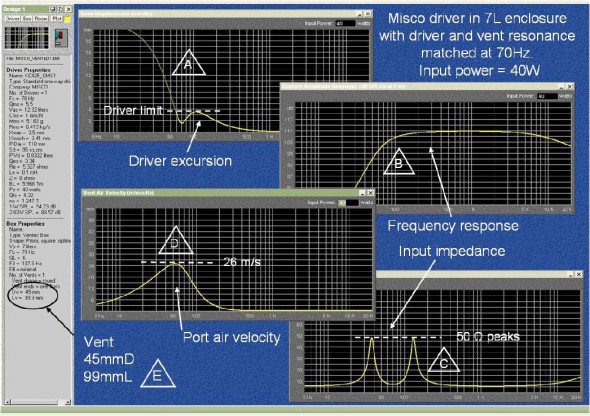
 Figure 1. BassBox6 prediction of Misco driver in seven liter vented enclosure with 40W input. The vent resonance and driver resonance are matched at 70Hz. Connect the letters with the following notes:
- (A) Bad news on excursion. Below 60Hz the driver runes wild. Only an HP filter can save it!
- (B) The -3dB point is ~100Hz. But this will be severely compromised by the requirement in (A) unless the filter is really steep.
- (C) Dr. Heaviside would be so happy to see this! The motional impedance rise, called Res, is ~45 ohms.
- (D) Pretty safe here at Mach 0.035.
- (E) Oops! Fitting a 10cm tube into this cabinet might be a problem—can’t get too close to the back wall.
.
Let’s try it out with BassBox6 Pro as seen in Fig.1. We have the MICSO driver and an enclosure to work with, so designing a port to resonate with the enclosure should not be too difficult, as seen in Fig. 1. Why is there a resonance at all? The port contains a volume of air that has mechanical mass, and it moves, representing kinetic energy. Air is heavy stuff at sea level: 1.2kg/m3 (dry). After transformation to acoustical units, this air mass, called Map resonates with the total compliance of the enclosure (including the mounted driver) that represents potential energy. Map is easy to calculate as: port area [ Sp (m2) * length (m) * 1.2kg/m3 ] / Sp2. The numerator is the mechanical mass and the denominator transforms it to acoustic mass. After canceling an Sp, then Map = (l * ρ) / Sp in kg/m4. Remember that this is for the air inside the port.
At the port resonance frequency, where the kinetic and potential energy run a bit wild with each other, the air velocity at the end facing outward radiates acoustic pressure. This suggests there is a radiation mass load that adds to the air mass inside the port.
This added mass depends upon how the port is terminated—is it flush with the enclosure wall, is it flared, or does it stick out? We need to know because the radiation mass effectively adds to the physical length of the pipe. The other end of the port inside the enclosure has a similar added mass issue.
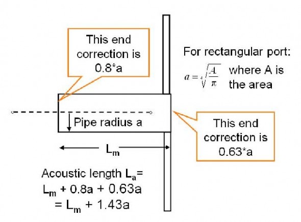
Many authors have addressed this and presented short-cut approximations. These corrections alter the effective mechanical length of the port so that the acoustic length is properly simulated. They are applied to each end of the port tube sepa- rately. A readable explanation is given in Kinsler et al in Chapter 9. With a = pipe radius, the empirical length corrections are simple: for a pipe sticking out, add 0.8*a; for a pipe that is flush to a wall, add 0.63*a where ‘a’ is the radius of the port. If the port is rectangular, then use the ‘a’ from the equivalent-area round tube. See Fig. 2.
Any open pipe termination in free air is an acoustic disconti- nuity that governs the suddenly expanding air flow. The exact shape of each end of the port has a profound effect on the harmonic behavior (think trumpet), but at very low frequencies (wavelengths much longer than the port),and at acceptable (see later) air velocities, that is not our concern.
One well-known loudspeaker manufacturer patented an elliptical flare (like you see on turbine engine cowls). My friend, a turbine engine expert, said. “..that was $%#&@ !–as long as there is no separation of the flow from the wall the shape is not important”. If there is separation and excessive turbulence in a reflex port the results may be audible. Old rule of thumb: never exceed Mach 0.1, about 76 miles per hour (34m/s) air velocity in the port. See also this AES paper and this patent. The aforementioned patent is described in detail in these JASA papers: Part 1 and Part II by Roozen et al.
These papers nicely illustrate the problem—the pipe itself is a tuned element (as an organ pipe), and the pipe emits a narrow band of energy at the λ/2 frequency that is modulated by the huff and puff of the port/enclosure resonant air flow. This is most prominent at the initial air flow—what organ builders call “chiff”, that lovely starting transient of a big diapason. Loudspeakers designers call it “chuffing” and hate it! Our port, at 13.3cm acoustic length, will have a “chuff’ (maybe more like a “modulated whistle”) principal frequency at ~1290Hz, hopefully, inaudible.
There will always be turbulence and viscous loss inside the pipe, and at the ends. Thus there is a dissipative loss we can call Rap, usually quite small compared to other acoustic losses. With a stiff enclosure and ‘normal’ port sizes, a Q of better than 5 can be achieved. This small loss can be ignored, or in some programs either port Q or the damping ratio can be entered.
Unfortunately, there is one serious disadvantage: the driver excursion below port resonance increases dramatically for con- stant input and requires a high-pass filter to control it. The excursion heads ‘north’ at a rate of four times per octave, or~12dB/octave. We must have a 2nd order (or higher) HP filter in line somewhere.
Notice that this matched ‘tuning’ has no apparent advantage over the closed box frequency response if you compare Fig.1 here to Fig. 8, Part 3. In Part 5 we will explore ‘detuning’ this double-tuned circuit and see if some additional advantages are available.
The kids running through the sewer pipe are bouncing off the walls, screaming, and some coming out the end try to go back around the outside, but bang into the fence surrounding the pipe outlet. Some run back inside the pipe and have no such problem at the input end
What have we learned? Probably more than you wanted to know about pipes, vents and ports. But they are a point of potential weakness in a bass-reflex design and all of the behavior mentioned here needs to be considered carefully in the design process. Systems engineering is the art of compromise!
A wonderful driver mounted in a well-built vented cabinet can make undesirable low-frequency noises from the port! It pays to stick your head in there to be sure all the screaming kids actually have left Loudspeaker Park. Maybe it’s time to call “Joe the Plumber”. dc

