Why 8 Ohms? – Part 1

Anyone who has messed with audio gear of any kind has run across “8 ohms.” Where did it come from and what does it mean?
“8 ohms” is found in loudspeaker specifications, amplifier specifications, and on wire gauge charts. Amplifier’s that are optimized for this load impedance are generally classified as “low impedance” (Low-Z) since the number “8” is numerically small. What’s the significance of “8 ohms?”
Many of today’s audio terms and practices originated early in the last century. That doesn’t make them antiquated. Most are as valid now as they were then, and tasked with the development of the technology today we would make the same choices. “The original story” on just about anything gets obfuscated with passing time, to the point where “the original story” may be completely lost. The following is a plausible explanation of the origin of “8 ohms” in audio systems but it’s not likely the whole story. The internet is at your fingertips.
The power grid, as we know it, began in the 1880s. The engineers of that day were tasked with electrical power generation and transport to the masses. For the United States, after some initial attempts, the objective became to provide every household with a 60 Hz alternating current utility power source. How much power? The average home in the US needs about 1500 watts on average, sometimes more sometimes less. A modern home has multiple circuits that can operate simultaneously. We’ll examine one of those circuits in this article.
A Utility Power Circuit
Power delivery is accomplished by a standardized “constant voltage” network. The voltage delivered to a home is 240 VAC, single-phase. This is typically split into two 120 VAC “legs” for most household circuits. The system is split-phase “constant voltage,” not because it’s always 120 VAC (within an appropriate tolerance) but because the voltage does not change under load. Plug in nothing or plug in everything, it’s still 120 VAC (Figure 1). The voltage is not affected by the presence of the load, hence it is “constant.”

Figure 1 – In a constant voltage distribution network all devices get the same voltage from the source. The current flow increases as more devices are added.
When a load is connected across the 120 VAC source (always in parallel) current will flow, as allowed by the load impedance. Impedance is opposition to current flow, so a lower number means that more current flows. The two extremes are an “open” circuit (infinite impedance, no current) and a short circuit (zero impedance, maximum current). A short can allow (or pull) so much current that things catch fire.
What Voltage?
When the system was being designed there were an infinite number of voltage choices for the utility power circuit. The US arrived at 120 VAC for mostly practical reasons. There are pros and cons to going higher or lower. A higher voltage increases the shock hazard to human occupants. A lower voltage reduces the allowable wire length to the appliance.
The available current also had to be established by design engineers. Make it too high and excess loading (too many things connected) could cause the wire insulation to melt. Make it too low and there might be insufficient current for some household appliances (looking ahead to automatic washing machines, clothes dryers, and air conditioning). They compromised at 15 A, with higher amperage requiring special connectors. Also, the full phase voltage of 240 VAC is “in the box” and available for the power-hungry products.
Given that the voltage is 120 VAC and the maximum current is 15 A, the minimum load impedance can be calculated using the power equation. A load of 8 ohms allows about 15 A of current flow. That’s the first (and most significant) occurrence of “8 ohms” that I can think of and it’s not in an audio circuit (Figure 2).
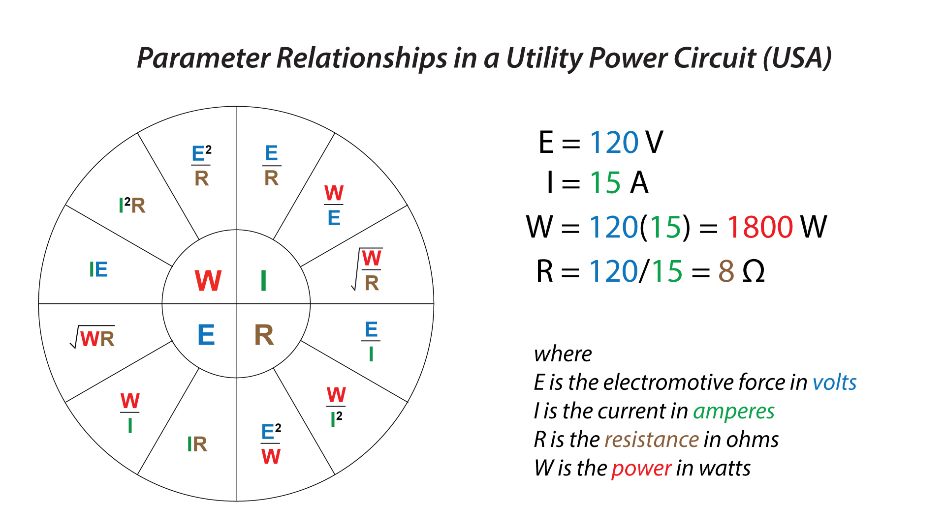
Figure 2 – The Ohm’s Law wheel shows the relationship between voltage, current, and resistance for a DC circuit. This is the simplest representation of an AC circuit for which the impedance is resistive. Note the 8 ohm minimum load resistance.
The objective of the circuit is to produce current flow through the load impedance. There are two ways to alter the current.
1. Adjust the voltage
2. Change the load impedance
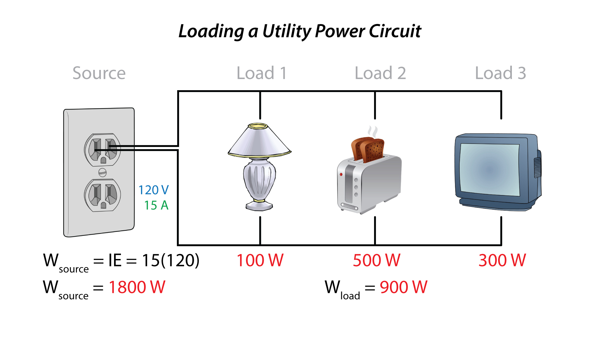
Figure 3 – The accounting required to properly load a circuit can be simplified if the current draw and impedance are replaced by a power rating. This is possible because the voltage is fixed at 120 VAC.
The Voltage Divider
Figure 4 shows a simple schematic for a household utility circuit. The source voltage of 120 VAC will distribute (or divide) across the impedances in the loop in proportion to their value. There are three impedances of interest.
1. The load impedance
2. The source impedance
3. The wire impedance
The objective is for all of the voltage to develop across the load impedance. This mandates that load impedance be (by far) the highest value in the loop. The source impedance and wire impedance both should approach zero. Neither can actually be zero, but they can be made very small when compared to the load impedance. The source impedance was established by the design engineer, and is necessarily “low.” The wire impedance is determined by the conductor material, its cross-sectional area, and length. Even though the wire is an impedance (a combination of resistance and reactance) when operating within our established parameters it can be simplified to a resistance. Let’s do that.
Figure 4 also shows a wire resistance chart for various gauges of copper wire. To minimize its influence on the load voltage, the total resistance should not exceed 5% of the load impedance value. We want all of the voltage to develop across the load and we don’t want the wire to get hot. The “5% rule” accomplishes both. A little number crunching reveals that AWG12 can be used to serve a load located 120 ft (37 m) from the source. That’s a reasonable gauge considering the cost of the wire and its flexibility. Unless you live in a mansion it’s probably long enough to reach those remote outlets.
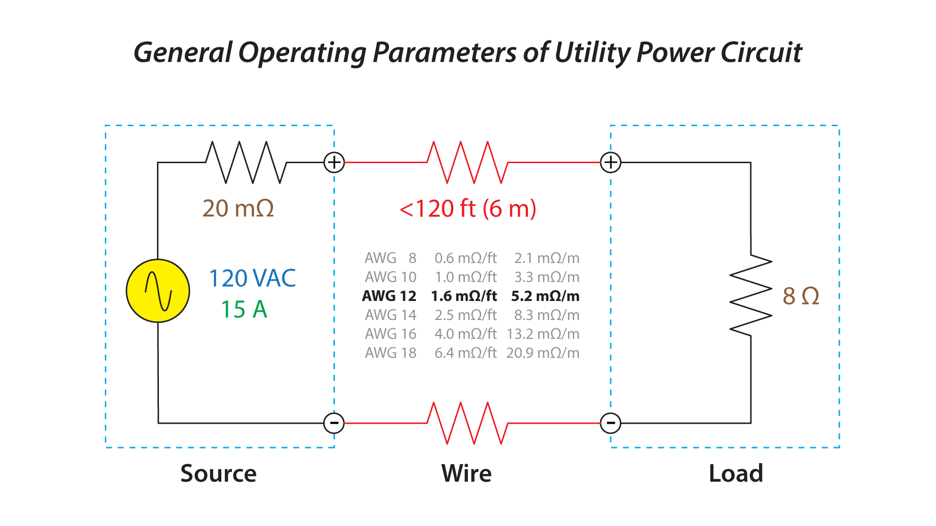 Figure 4 – A household utility circuit is a voltage divider.
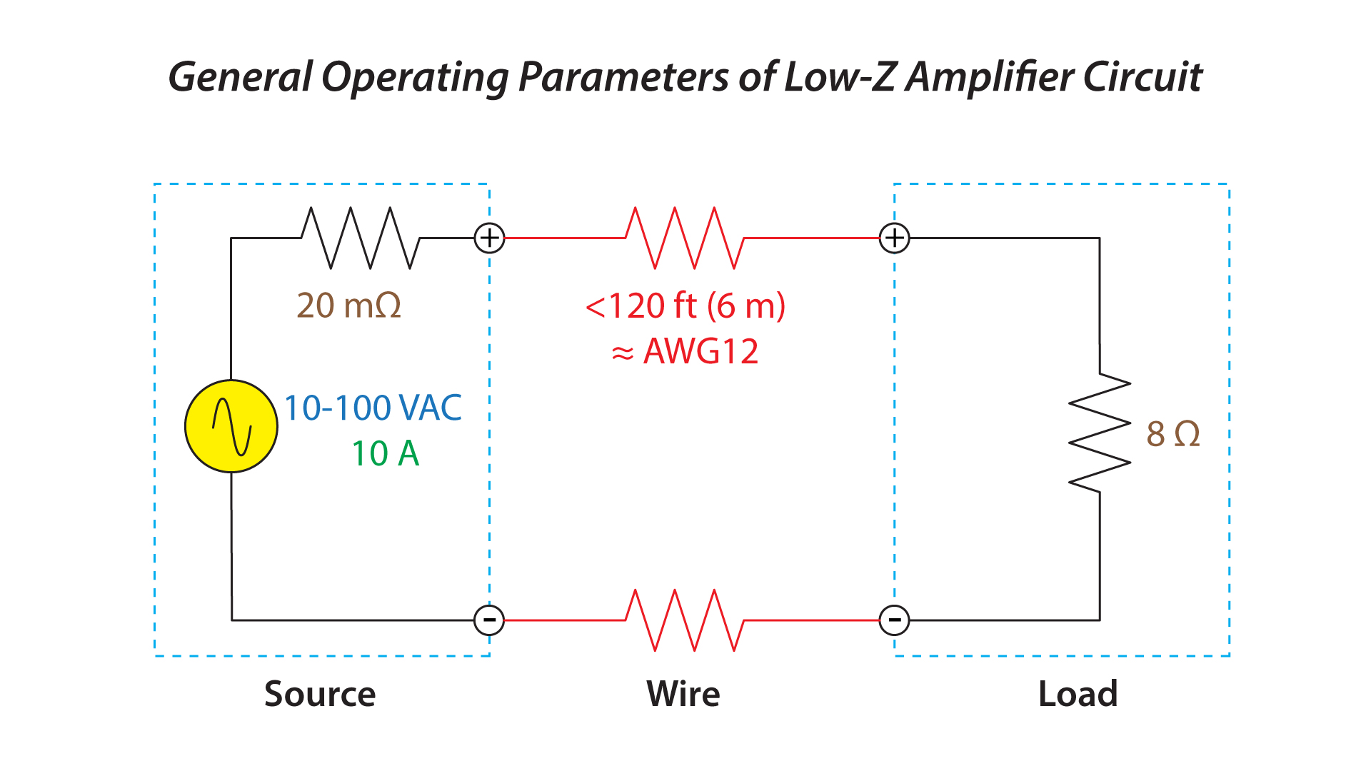
Emblazon Figure 4 into your psyche. If you substitute a broadband, variable voltage source (an audio signal) for the 120 VAC fixed-frequency source you have an audio amplifier/loudspeaker circuit.
The use of 8 ohms as the minimum load in a utility power circuit accomplishes the following:
1. About 1800 W of continuous power
2. About 15 A of current
3. Acceptable voltage drop (line loss) from AWG12 copper wire up to 120 ft
Higher Than 8 Ohms
In audio systems sometimes cables need to be longer than 120 ft (37 m). Two possible solutions are
1. Use a larger wire gauge (expensive and cumbersome)
2. Use a step-down transformer at the load
A step-down transformer accomplishes two things:
1. It reduces the applied voltage to a lower value (hence the name).
2. It increases the loudspeaker’s impedance to a higher value, which reduces the current draw on the amplifier. This allows longer cable runs, multiple loads in parallel, and higher wire gauges (thinner wire). All are necessities for distributed audio systems.
Figure 6 shows the voltage divider with a step-down transformer at the load. The numerically high load impedance as seen through the transformer makes this a “high-impedance” distribution system. For audio circuits the distribution voltage is a standard value, most commonly 70.7 VAC or 100 VAC. These are sine wave reference values. Of course the actual audio signal can be any voltage below the peak value of this reference voltage. This scheme is strikingly similar to a household utility power circuit, where the power supplies of the various devices (internal or external) provide the voltage reduction.
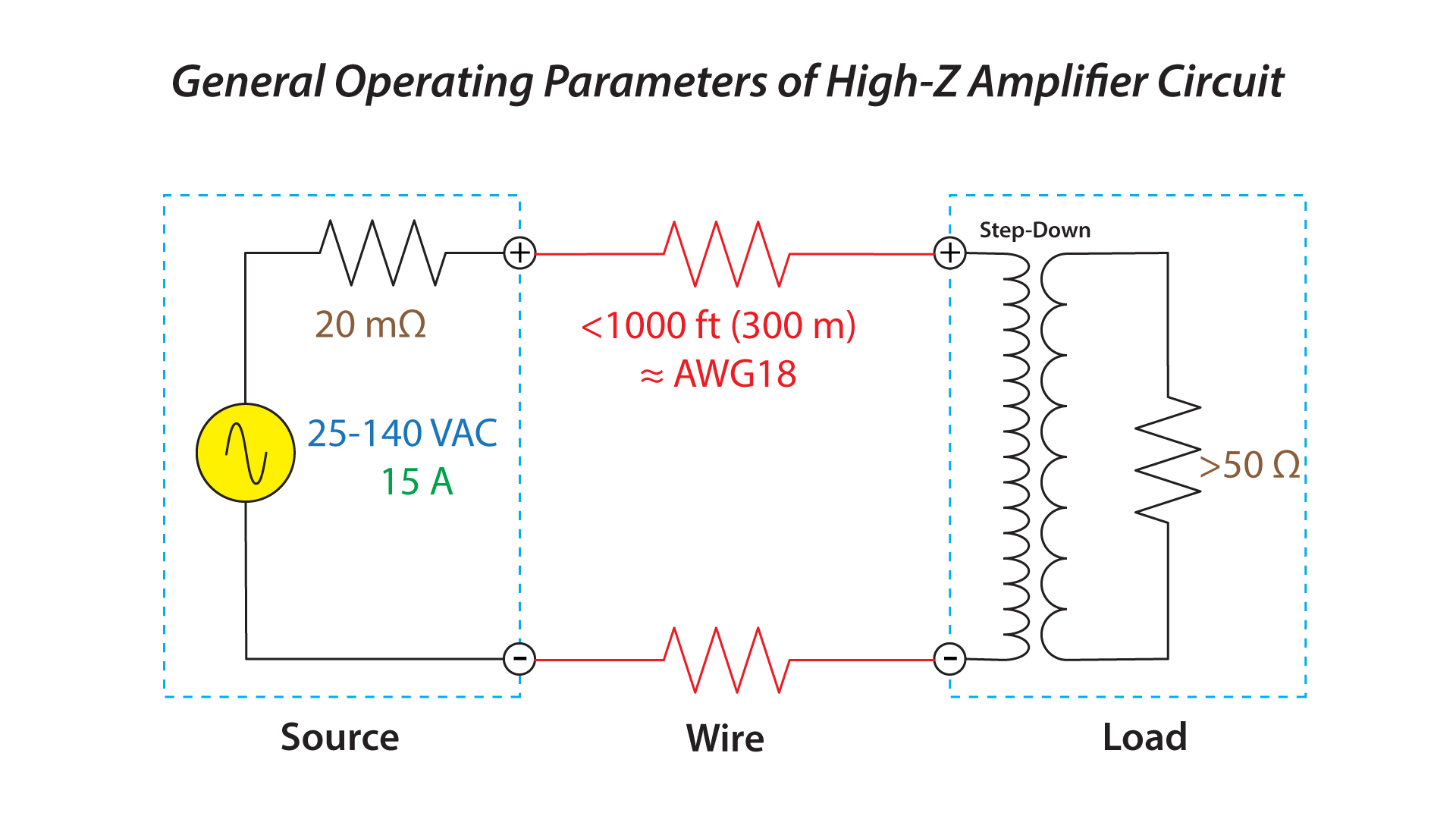 Figure 6 – Increasing the load impedance beyond 8 ohms reduces the current draw from the amplifier. The increased minimum impedance can allow more loads in parallel and a smaller wire gauge (larger number).
Lower Than 8 Ohms
Another notable exception is car audio. Here we are operating from a 12 VDC battery. The voltage is low, but the available current is very high – hundreds of amps! How is this circuit different from that used for utility power and low-Z amplifiers?
1. 120 VAC presents an increased shock hazard for the vehicle’s occupants.
2. The maximum cable length in a car should be WELL below 120 ft.
3. The voltage is lower (12 VDC) and the available current is much higher (hundreds of amps!).
These conditions suggest a distribution scheme that uses lower voltage and higher current than utility power circuits and public address systems. The circuit parameters can be scaled down accordingly.
1. In an automobile the loudspeaker impedance is often lower than 8 ohms. Four and 2 ohms are common, and paralleled subs may approach 1 ohm.
2. The amplifier’s output voltage rarely exceeds 50 VRMS.
3. The circuit current can be tens of amperes (or more). The lower voltage (and higher current) necessitates large wire gauges to minimize the line loss, even for relatively short cables. AWG8 (and larger) is common in vehicles.
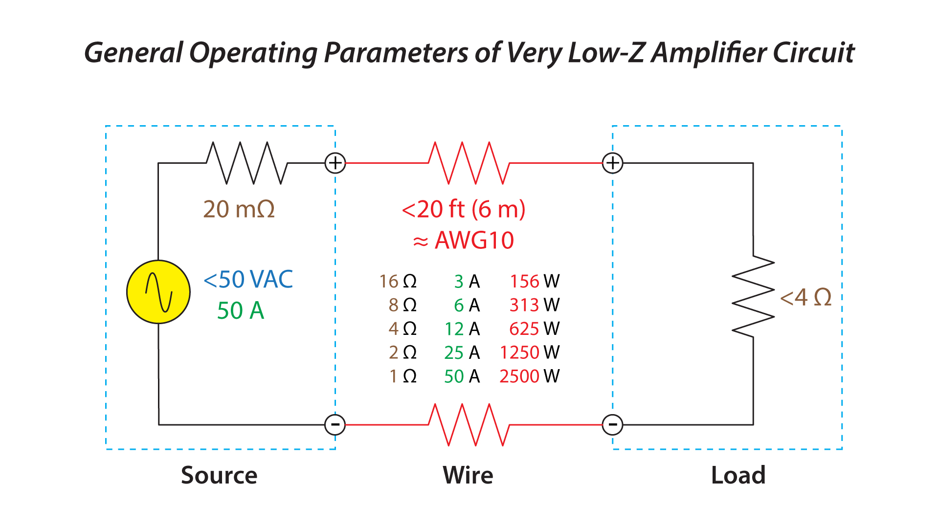 Figure 7 – Automotive amplifiers have high available current and only need short cable runs. Very low impedance loudspeakers can be used under these conditions.
Some take-aways…
Once the basics of power distribution are understood, applying the principles to the various sound system types is just a matter of scale. Figure 8 shows the general operating parameters based on amplifier type. Note the central role played by an 8 ohm load.
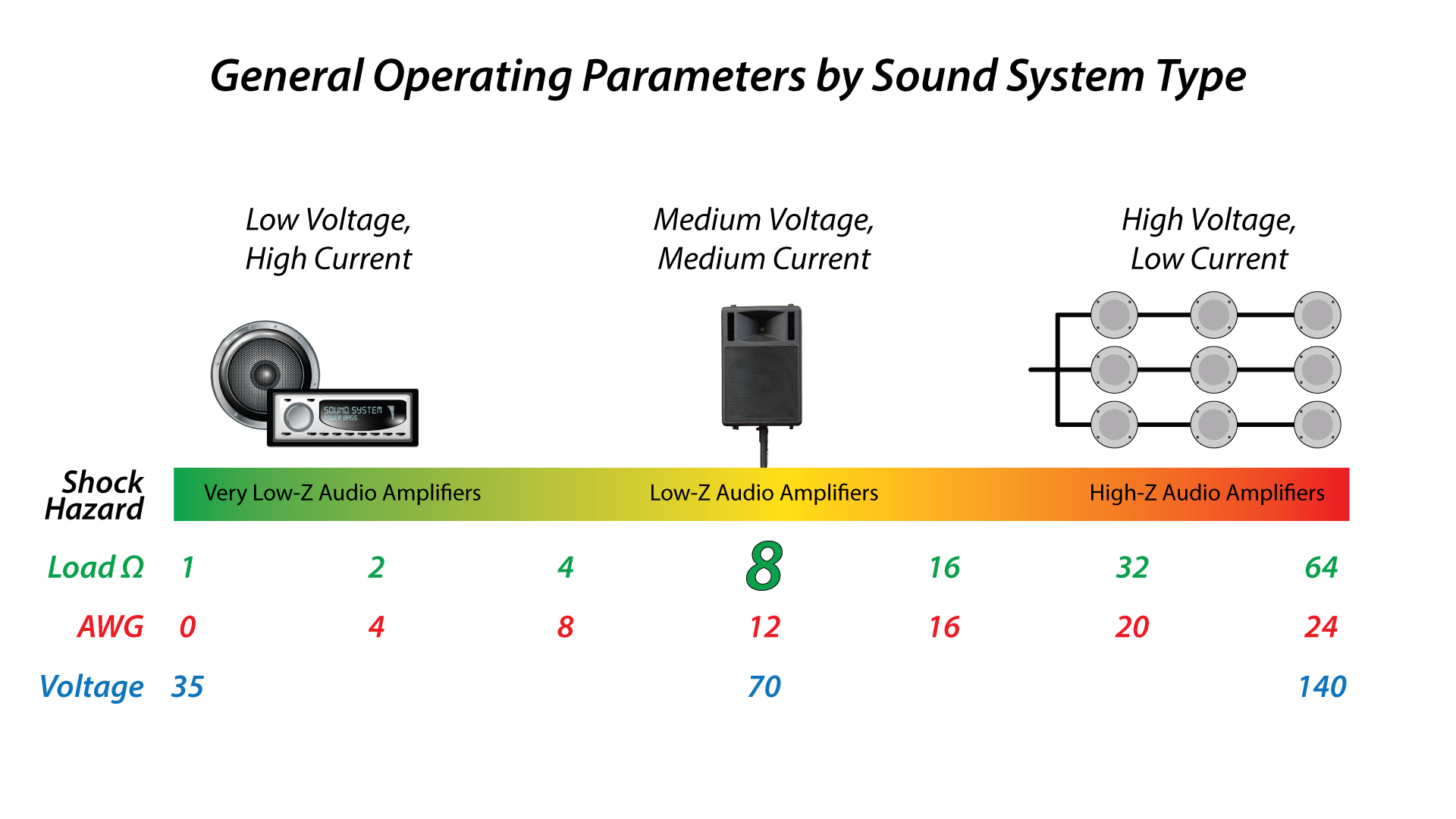
Figure 8 – The load impedance in various types of audio systems can be about any value. 8 ohms serves as a good reference value, with higher and lower impedances representing special cases.
- Efficient power distribution is governed by distance, with the wire resistance as the main nemesis. We don’t want the source voltage developing across the wire resistance instead of the load. This dictates the appropriate values for the voltage divider circuit.
- The general audio solution is the use of the same values found in utility power circuits. This produces a balance between available power, the required wire gauge, and safety. AWG12 is a very common wire gauge in “low impedance” amplifier applications. In my contractor days we bought it in bulk because it worked for most systems.
- When multiple loads and long cable runs are necessitated, a step-down transformer at the loudspeaker can increase the load resistance, reduce the source voltage, limit the current, reduce the required AWG, and allow hundreds of parallel loads. Utility power distribution works the same way.
- When the max cable length is short and a shock hazard exists, the whole scheme can be scaled down to the lower voltage, higher current model used in automobiles. These systems are generally characterized by lower load impedance, higher load current, and larger wire gauges than utility power and public address systems. Large, low-cost, car audio amplifiers are made possible by the very large direct current source under-the-hood. pb

