The Magic Behind Multi-Pattern Mics
Theory and Practice – By Dale Shirk
This article will take a closer look of how multi-pattern mics work.
Multiple pattern microphones have been used in studio work for years, and today are becoming very common in live sound as well. Low cost studio type mics are readily available. Even miniature podium gooseneck mics are available with pattern switching. Perhaps it’s time to take a closer look at how they work.
There are two basic types of mics, those which respond to pressure, and those which respond to velocity. In a free field a sound wave will have both pressure and velocity components of course. Pressure does not have any specific direction associated with it, and a pressure responding mic is omnidirectional. The sound is only allowed at the front of the diaphragm. The rear of the diaphragm is enclosed.
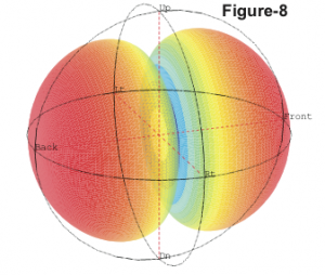
Velocity has a directional component, and a velocity mic will have maximum response on one axis, and minimum response on the other two axes. This is the Figure-8 pattern. Sound is allowed equally at the front and rear of the diaphragm. Sound from the front will be positive polarity. Sound from the rear will have velocity in the opposite direction and be opposite polarity.
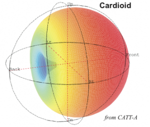
Perhaps the most familiar and useful polar pattern is the cardioid. It responds to the pressure gradient – to the difference in pressure at two different locations. There are several ways to accomplish this. One is to sample both the pressure and the velocity in one direction. By mixing the outputs of an omni and a figure-8 mic capsule located as close together as possible, we can obtain a cardioid pattern. Actually by varying the mix levels of the two mics we can obtain a whole family of polar patterns from omni and sub-cardioid, thru cardioid, supercardioid and hypercardioid to figure-8.
The second way to achieve a cardioid polar pattern is to use two omni mics slightly displaced along the velocity axis, thus sampling the pressure at two different points. These two mics are mixed out of  polarity with a small delay added to the rear one, equal to the time-of-flight between the capsules. This yields a cardioid pattern which holds for all frequencies where the wavelength is more than 4 times the spacing between capsules. It also results in a frequency response which falls off at 6 dB/octave as frequency goes down. This falling response can be equalized out, either electrically or acoustically. Again the polar response can be varied through the whole family of patterns by varying the levels and delay of these two capsules.
The third and most direct way to achieve a cardioid polar pattern is to allow sound to the front of the diaphragm unrestricted, but to construct the rear of the capsule so as to locate the rear pickup point displaced in space, and use the acoustic path to the rear of the diaphragm to provide the delay. The acoustic properties of the chamber, diaphragm mass and suspension, etc. provide the needed equalization.
Let me stress again for reasons that will become obvious shortly, that regardless of the actual mechanism used to achieve a directional polar pattern, it is in essence evaluating the pressure difference between two points in space. At low frequencies, with long wavelengths, the two sample points are only a small fraction of a wavelength apart, with only a little pressure difference between them. The majority of the wave at low frequency is canceled out, but what’s left is boosted again to become useful signal.
Multiple pattern microphones all use some combination of two capsules. Miniature gooseneck mics meant for podiums use two omni capsules. Studio condensers usually use two cardioids in a back-to-back configuration. In actual construction they use two diaphragms separated by a short distance and share parts of the same rear chamber. The outputs of the two capsules can be combined in-polarity to yield an omnidirectional pattern. A single capsule by itself is of course the cardioid pattern. The two capsules combined reverse-polarity yields the figure-8 pattern. Again, by varying the mix levels between the two capsules, the whole family of patterns can be created.
Anyone with the interest to read this far, already knows that most cardioid microphones have what’s called “proximity effect.” This is the boost in bass for sources close to the microphone. Let’s look a little closer at why this happens.
The pressure gradient principle depends on equal level arriving at each pickup point, front and rear. For sources a large distance away this is a valid assumption. As the source gets closer however the the slight difference in relative distance to the source translates to a slight difference in level due to simple inverse-square law. As I pointed out above, as frequency goes down the level is falling by 6 dB/octave. This is then equalized out. Several octaves below the design frequency which is 1/4-wavelength spacing between pickup points, there is significant cancellation in the pickup physics and accompanying EQ boost, either electrical or acoustic, to make it up. If you are working with two signals canceling each other to the tune of 30 dB or more, even a slight level difference will wreck it hugely.
Proximity effect is in fact the wrecking of the expected cancellation by slight level difference. As frequency goes down the mic is looking for smaller and smaller level differences and boosting them more and more. When there is additional level difference caused by different path lengths, there will be more signal and more to boost. A source close to the mic from the front will have slightly higher level at the front pickup than at the rear pickup. At 90 degrees off-axis there is no distance difference and no proximity effect. At 180 degrees the rear pickup is slightly closer and the cancellation is again wrecked causing more proximity boost, but this time the rear pickup gets more signal, which is the out- of-polarity component. The rear proximity boost is reverse polarity.
Thus we see that the polar pattern of the proximity effect is a figure-8, regardless of whether the cardioid is derived from two omnis, an omni and a figure-8, or a single diaphragm with mechanical-acoustical resistance on the rear port.
When an omni pattern is derived from two back to back cardioid capsules added in-polarity, each capsule will exhibit its inherent proximity boost, but the front lobe from the front capsule which is positive polarity, and the rear lobe from the rear capsule which is negative polarity, will cancel each other out. Therefore the omni still has no proximity effect.
When a figure-8 pattern is derived from two back- to-back cardioid capsules added reverse-polarity, the proximity patterns will add together, giving it a greater proximity sensitivity than a cardioid. This is in fact the same as a native figure-8 microphone, such as a ribbon mic.
Proximity effect is not generally significant in cardioid speakers because we usually can’t live with working many octaves below design frequency and the inherent cancellation that goes with it.
Directional microphones with reduced proximity effect have been developed. These use some form or other of separating the pickup points by a greater distance at lower frequencies. Either they use multiple capsules with a crossover, or they use multiple rear ports with the more distant ones used for lower frequencies. This reduces the boost requirements and the proximity effect that comes with it.
These properties of directional microphones are inherent in the pressure gradient principle as laid out by Harry Olson, and are not dependent on the actual mechanism used to derive the directivity. They explain why you might experience unexpected results when working in tight quarters, such as around a drum kit. ds
