The Floor-Bounce-Effect – Mic Placement for Equalization
Pat Brown addresses the importance of considering the floor-bounce-effect in the equalization process.
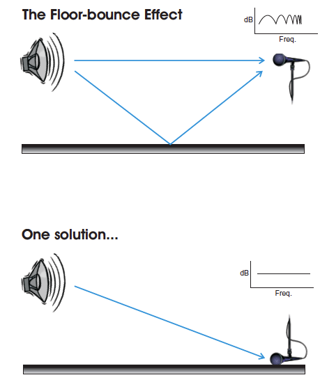
When a microphone or listener is positioned above the floor plane, the reflection produced by the floor modifies what is heard by the listener. This “floor- bounce effect” (FBE) is a normal part of the way that we listen to loudspeakers when an audience is not present to absorb this first-order reflection. This effect must be considered during the equalization process, as it dramatically affects the response observed on high resolution analyzers.
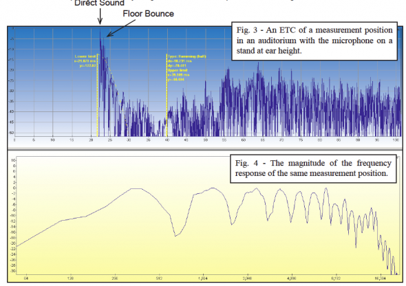
The FBE produces ripples (a comb filter) in the frequency response measured as at a discrete listener position. At one position, the effect could be minimum-phase and “correctable” with equalization. The problem is that the time offset between the direct arrival and the floor reflection is not a global parameter of the space. Each listener position has a unique time-distance relationship to the loudspeaker and its first-order floor reflection.
This means that any electronic compensation used at one seat will be incorrect for most of the others.
A Dramatic Demonstration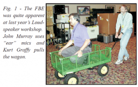
The position-dependence of the floor-bounce effect was dramatically demonstrated by John Murray and Kurt Graffy during the Syn-Aud-Con Loudspeakers Workshop in August 2002. John was outfitted with ear-mics and placed on a wagon (Figure 1). The audience listened through John’s ears (using infrared headsets) as Kurt pulled him away from the loudspeaker. As the loudspeaker-to-listener distance was increased, the decreasing time offset between the direct sound and the floor bounce produced a series of peaks and nulls that moved upward through the spectrum. This proves that it is not possible to compensate for the effect with electronic equalization at multiple listener locations. An old adage of equalization is “If you can’t fix it, ignore it!” This can be done by placing the mic on the floor (as a “boundary” mic – Figure 2) during the equalization process, effectively removing the time offset between the direct arrival and the floor reflection.
Frequency-Dependence
At low frequencies, the long wavelengths make the floor-bounce effect more consistent over the listening area, since the time-distance offset relative to frequency (phase differential) is small and doesn’t change much from seat-to-seat. “Space-loading” of loudspeakers occurs when the long (low frequency) acoustic waves couple with nearby surfaces and produce a “bass rise” at the listener position. Boundary-loading effects must often be equalized to achieve the desired response. Unfortunately, boundary loading “plays out” as frequency increases and the upper-spectrum acoustic response becomes unique at each listener position. One cannot simply equalize for a “flat” magnitude response in this part of the spectrum at a single listener position. If a ground plane measurement is not possible, the FBE can either be ignored, or smoothed using spatial averaging, a 1/n octave display, or a smaller time window.
Prediction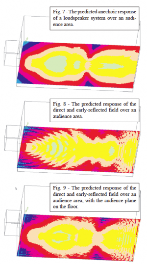
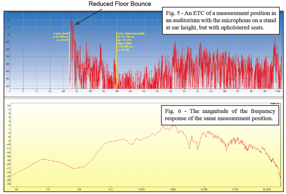
The floor-bounce effect is entirely predictable. Figure 7 shows a sound-pressure level map of an audience area of the anechoic (no reflections) response of a loudspeaker. The “Reflection” option of the Ulysses™ calculation algorithm was then used to calculate the direct sound field with the inclusion of the first 35 ms of the room’s impulse response at each position. The floor bounce is often the most dominant refection in this time span, and it’s position-dependent effect is very apparent on the LP map (Figure 8). If the listening plane were placed on the floor rather than at ear height, the response becomes more uniform over the audience area (Figure 9). This is exactly what is accomplished by using a boundary or PZM™ microphone. Ignored during system equalization, the FBE is allowed to occur naturally at each listener position or disappear completely in the presence of an absorptive audience or upholstered seats.
Less May Be Better
The proliferation of high resolution analyzers has made the floor-bounce effect a potentially bigger problem than it once was. With 1/3 octave analysis, the effect was somewhat smoothed, if it was even observed at all. With the high resolution displays of modern analyzers, the effect is very apparent and there is a temptation to “fix” the comb filtered response with parametric equalization. Many an audio practitioner has spend hours trying to achieve a flat magnitude response, only to find that better sound was achieved by simply bypassing the excessively adjusted equalizer. Automatic EQ algorithms are also easily fooled by a comb-filtered response and will methodically implement as many filters as are necessary to smooth the response. This is where the “human” side of equalization is alive and well, as an experienced practitioner will recognize the problem and work around it. pb
Value Systems – Wavelab 4.0
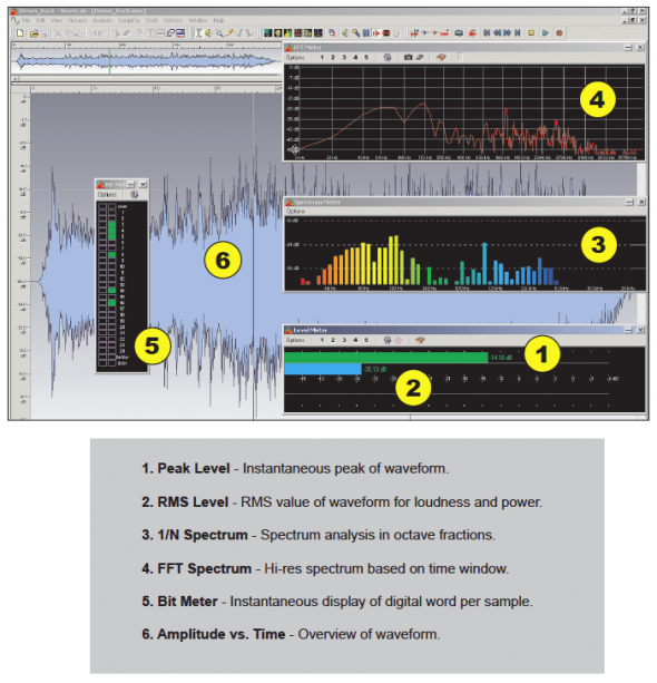
The inherent complexity of audio signals make them difficult to monitor and measure. Several useful methods exist, each with its own set of strengths and weaknesses. The graphic below illustrates some of possibilities. Each numbered plot represents a valid way to observe the audio signal. It reminds us that any single view of the waveform is blind to some of its characteristics. Plots 1 and 2 are used to monitor level, while 3 and 4 are used to observe spectral content. Plot 5 can be used for assurance that the dynamic range capabilities of a component are being fully utilized, and 6 gives a “birds eye” view of the information after-the-fact.
The screenshot is from Wavelab 4.0™. pb

