Understanding Horn Directivity Control
Charlie Hughes will help you understand more about horn directivity control.
Horns are often used in loudspeaker systems for a variety of reasons. One may be to provide increased acoustical loading to the driver attached to the horn. This helps to increase the sensitivity/efficiency. Another may be to provide some control over the radiation pattern of the driver attached to the horn. It is this directivity control aspect upon which we will focus our attention for this article.
In 1975 Don Keele presented a paper at the 51st Convention of the Audio Engineering Society that introduced the modern Constant Directivity horn. This new horn design (new at that time) combined an exponential throat section, to provide good loading at lower frequencies, with a conical or straight wall section that provided a more uniform coverage pattern in the higher frequency region than a pure exponential horn. In this paper he noted the relationship between the coverage angle of the horn, the low frequency loss of directivity control, and the horn mouth size;
d = the mouth dimension of the horn (either horizontal or vertical)
θ = the coverage angle of the horn (horizontal or vertical)
fo = the low frequency loss of directivity control, θ (horizontal or vertical)
and K is a constant with an empirically derived value of 1×10^6 in*deg*Hz or 2.54×10⁴ m*deg*Hz
From this equation we can determine the horn mouth dimension necessary to yield directivity control down to a certain frequency. For a fixed coverage angle, a larger mouth dimension is required to maintain this coverage to a lower frequency. For every octave lower we want directivity control (halving of frequency) the mouth dimension must double.Similarly, if the coverage angle is made smaller the horn mouth dimension must increase to maintain this coverage angle to a given frequency. For every halving of the coverage angle the mouth dimension must double.
This larger mouth size for a smaller coverage angle seems counter intuitive to many people when they are first presented with it. However, due to those pesky laws of physics this is the way things work. It is not unlike the same principles that govern the behavior of a line array. To have the narrow vertical coverage angle, which most of us associate with line arrays, to a low frequency requires a long line array.
If we have a horn with a known coverage angle and we also know the mouth dimension we can rewrite this equation to solve it for low frequency loss of directivity control.
Above this frequency the coverage angle, or beamwidth, should be fairly constant. Below this frequency, however, the beamwidth should increase as we lose directivity control. This is an extremely important point to keep in mind when evaluating potential loudspeakers for use in system designs where good directivity control is required. Loudspeaker spec sheets all too often reference a nominal coverage pattern with little qualification as to the frequency region over which this beamwidth is actually maintained. As we will see later, omitting this information and an erroneous assumption on the designer’s part may yield less than desirable end results.
To determine the coverage of a horn below the frequency at which is starts to lose directivity control we can once again rewrite Equation 1 solving for the coverage angle to get,
Note that we have substituted any frequency,f, for the low frequency loss of directivity control, f0. This is valid so long as we restrict it to frequencies lower than the low frequency loss of directivity control. At frequencies higher than this the beamwidth should be relatively constant at the design coverage angle.
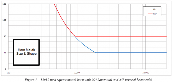
Graphing Equation 3 will indicate how the loss of directivity control progresses with decreasing frequency. This is shown in Figure 1 for a hypothetical horn with horizontal and vertical coverage angles of 90° and 45°, respectively. The horn has a 12 inch (30 cm) square mouth. A real horn might not be quite so well behaved in the region around the initial loss of directivity control frequency. This is intentionally not shown as its cause is beyond the scope of this article and to simplify the presentation of the relevant topic.
As we can see in the graph the horizontal beamwidth of 90° begins to increase at just above 900 Hz. The 45° vertical beamwidth begins to increase at approximately 1.8 kHz. Referring back to Equation 2 we can see why this occurs. The vertical beamwidth is half the value of the horizontal beamwidth. The horn mouth is 12 inches (30 cm) in both the horizontal and vertical planes, d is constant. Thus, the vertical loss of directivity control frequency, fov, is twice that of the horizontal loss of directivity control frequency, foh.
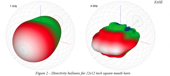
This is also illustrated in the directivity balloons shown in Figure 2. At 4 kHz the 90° x 45° coverage pattern is well maintained. At 1 kHz the loss of vertical directivity control can be appreciated as the coverage pattern appears almost axisymmetric. This behavior is also suggested by the beamwidth graphs in Figure 1. At 1 kHz the horizontal and vertical beamwidth are both approximately 90°.
In general, square mouth horns will have a ratio of the frequencies for horizontal to vertical loss of directivity control that is the same as the ratio of the vertical to horizontal coverage angle. For our example of 90° and 45° this is exactly the case as the ratio is 2:1. If the horn, with the same 12 inch square mouth, had a vertical beamwidth of 60° we would expect the ratio to be 3:2 for the 90° x 60° horn. This would place the vertical loss of directivity control frequency at a bit over 1.35 kHz.
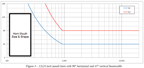
In order for the loss of directivity control frequencies to be the same for both the horizontal and vertical beamwidth, the more narrow coverage angle must have a mouth dimension that is larger by the ratio of the coverage angles. Let’s say that we want to modify our example horn for this to occur. Our coverage angle ratio of 2:1 would mean the vertical mouth dimension, height, would need to be twice that of the horizontal mouth dimension, width. So we would now have a horn mouth that is 12 in (30 cm) wide and 24 in (61 cm) high.
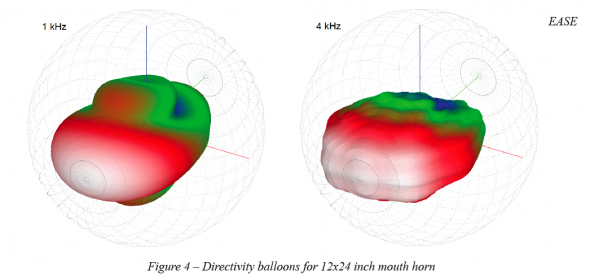
This can be verified by employing Equation 1 to calculate the new required height dimension. With this new height, Equation 3 may again be used to graph the beamwidth (Figure 3). The directivity balloons for this 24 inch tall horn (Figure 4) show the improved directivity control at 1 kHz compared to 12 inch tall horn (Figure 2).
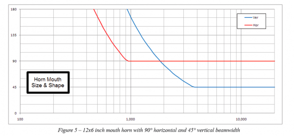
What about a more commonly seen horn, one with a height much smaller than the width? For 90° x 45° horns from some manufacturers mouth dimensions of 12 in (30 cm) x 6 in (15 cm) would not be out of the ordinary. Again, we will use Equation 2 to calculate the new frequency for the vertical loss of directivity control with our more commonly dimensioned horn. This turns out to be 3.7 kHz. Using Equation 3 to graph the beamwidth yields Figure 5.
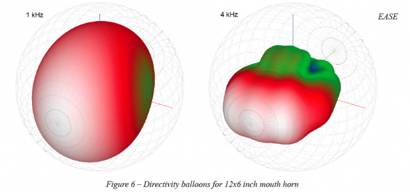
Here we see something very interesting not present in the previous graphs. Below 2 kHz the vertical beamwidth is actually greater than the horizontal beamwidth! This is sometimes referred to as “pattern flip”. The vertical coverage pattern of the horn, which is supposed to be narrower than the horizontal coverage pattern, is now the broader coverage angle. In other words, the horizontal and vertical beamwidth have flipped with respect to which is greater and which is lesser. This is particularly noticeable when examining the directivity balloons shown in Figure 6.
As mentioned earlier, if the spec sheet for a loudspeaker using a horn of similar dimensions merely gave the intended, or nominal, coverage angles with little or no information as to the frequency range over which the coverage angles were maintained one might erroneously believe that the stated beamwidth is valid for a much larger frequency range than is actually possible. As such, the loudspeaker performance shown in Figure 5 and Figure 6 may not work well for applications requiring good directivity control in order to facilitate adequate speech intelligibility. The intended vertical beamwidth of 45° is only achieved above 3.7 kHz. Below this frequency quite a bit of acoustical energy could be put into areas where it is not desired. This will become noticeable when mapping the coverage of a loudspeaker using one of these types of horns in a room. The other item that may be observed is that below 2 kHz the loudspeaker may perform better if it was turned on its side. This is also seen in Figure 6.
As with most engineering exercises there are several items that must be balanced when it comes to the directional performance of horns. Narrow coverage angle, the desired low frequency for maintaining the coverage angle, and small horn size; pick any two. The two that are chosen will dictate what the third must be. One can’t arbitrarily have all three at the same time.
I hope this has helped to explain a bit about how the frequency dependent directivity of a horn relates to its size. Small horns simply can’t yield small coverage angles at low frequencies. Beware of those that attempt to advise, or advertise, differently. ch

