Polarity 101 – Some subtleties regarding device polarity
by Pat Brown
This article will help you understand polarity and ways to test polarity.
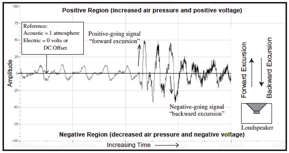
Good sound system installation practice dictates maintaining proper signal polarity from system input to system output. An audio signal waveform always swings above and below some reference point. In acoustics, this reference point is the ambient atmospheric pressure. In an electronic device, the reference is the 0VA reference of the power supply (often called “signal ground”) in “push-pull” circuits or a DC offset in class A circuits.
Let’s look at the acoustic situation first. An increase in the air pressure caused by a sound wave will produce an inward deflection of the diaphragm of a pressure microphone (the most common type). This inward deflection should cause a positive going voltage swing at the output of the microphone, as well as each piece of equipment that the signal passes through. Ultimately the electrical signal will be applied to a loudspeaker, which should deflect outward (toward the listener) on the positive going signal. Think of the mic diaphragm and loudspeaker diaphragm moving “in tandem” and you will have the picture. Since most sound reinforcement equipment uses bipolar power supplies (allowing the audio signal to swing positive and negative about a “zero” reference point), it is possible for signals to become inverted in polarity (flipped over). This causes a device to output a negative-going voltage when it is fed a positive- going voltage. If the loudspeaker is reverse-polarity from the microphone, an increase in sound pressure at the microphone (compression) will cause a decrease in pressure in front of the loudspeaker (rarefaction). Under some conditions, this can be extremely audible and destructive to sound quality.
System installers should always check for proper polarity when installing the sound system. There are a number of methods, some simple and complex. Let’s deal with them in order of complexity, starting with the simplest and least costly method.
The Battery Test
Low frequency loudspeakers can be tested using a standard 9V battery. The battery has a positive and negative terminal, and the spacing between the terminals is just about right for most woofers. The loudspeaker cone will move outward when the battery is placed across the loudspeaker terminals with the battery positive connected to the loudspeaker positive. While this is one of the most accurate methods for testing polarity, it doesn’t work for most electronic devices or high frequency drivers. Even so, it’s probably the least costly and most accurate way to test a woofer.
Polarity Testers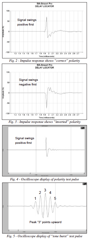
There are a number of commercially available polarity test sets in the audio marketplace. The set includes a “sending device” that outputs a test pulse (Fig. 4) through a small loudspeaker (for testing microphones) or an XLR connector (for testing electronic devices) and a “receiving device” that “collects” the signal via an internal microphone (loudspeaker testing) or XLR input jack. A green light indicates correct polarity and a red light indicates reverse polarity. The “receive” unit can be placed at the system output (in front of the loudspeaker) while the “send” unit is systematically moved from device to device toward the system input. A polarity reversal will manifest itself by a “red light” on the receive unit.
The Oscilloscope
An oscilloscope can be used to view the actual acoustical or electrical waveform. As such, it makes an excellent polarity tester. The waveform used can be the “pulse” from a polarity tester or a tone burst (such as the ones on the Syn-Aud-Con Test CD for Sound Reinforcement Systems). The tone burst test is especially useful since different frequencies can be selected (one-third octave centers). This allows a device to be tested in the middle of its band pass and away from crossover devices whose phase distortion can make it difficult to interpret the results. Figure 5 shows the tone-burst test and how to interpret it.
Impulse Response Tests
The impulse response is perhaps the most fundamental of audio and acoustic measurements. We have described it in detail in our Tech Topic series (A Primer for Performing Acoustic Measurements). The polarity of a loudspeaker or electronic device can be determined from observing its impulse response (Figs. 2 and 3). This is probably the only way to test flown loudspeakers from a remote position.
It is best to test the polarity of multi-way loudspeakers individually, since all of the individual components may not be polarized the same.
Polarity Confusion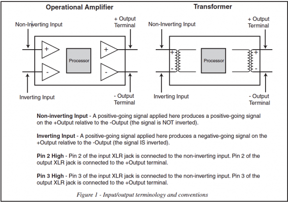
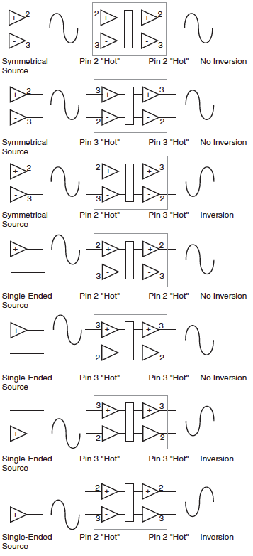
A confusing aspect of device polarity centers around the “pin 2 high” or “pin 3 high” issue. Figure 1 shows a diagram of a typical audio processor whose input 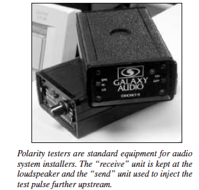 and output interfaces are realized with either an operational amplifier or a transformer. Each has two input terminals, one which does not invert signal polarity (called the noninverting input) and one which does (called the inverting input). According to the AES standard, pin 2 on an XLR connector should be connected to the non-inverting input and pin 3 to the inverting. Some manufacturers ignore the standard and connect their devices in the opposite manner. While this does not cause a polarity reversal for mid-signal path processors with balanced inputs and outputs (the relative polarity of the device is correct), it can cause inversions when interfaced with unbalanced equipment. The most common examples might be with tape decks or CD players at the system input and power amplifiers at the system output. Extra care should be taken when interfacing with these devices to avoid inadvertent polarity reversals. This is especially important in systems with multiple microphones and/or loudspeakers, as mispolarized devices can cause severe cancellations in overlapping patterns.
Figure 6 shows some common configurations encountered when interfacing audio gear. Transformers will work in a manner similar to the operational amplifiers shown with regard to polarity. Note that inversions only occur when interfacing with unbalanced gear. An exception is the case where a device reverses signal polarity internally. An advantage of balanced inputs and outputs is that polarity corrections can be made with a simple wiring change at the offending device’s input or output (swap connections to pins 2 and 3). In the case of unbalanced gear, it is necessary to first balance the input or output using a suitable device (transformer or op amp). The correction can then be made by swapping the wires.
Under some conditions, polarity reversals are not audible. This does not mean that checking and maintaining correct polarity is not important. Murphy’s Law guarantees that sooner or later a problem will arise that can be traced back to something as simple as a mis-wired cable. Also, polarity is sometimes intentionally inverted to achieve some desired end result. Be careful not to “correct” an intentional reversal. pb
Special thanks to the Syn-Aud-Con listserv for their observations and contributions on this subject.

