Take a walk in Loudspeaker Park with me – Part 3 Impedance
Campbell’s Corner – By Dick Campbell
Dick Campbell continues with his series of investigations into the impedance and other properties of loudspeakers.
It’s time for some fine tuning. If a slightly larger box is acceptable, then setting the target frequency to 100Hz gives us a box volume of 7.9 liters (a cube of 20 cm per side inside dimensions) and a Q of 0.53. This sets the actual -3dB point to just about 105Hz. This is a much better use of this driver in a sealed-box design, and it is an acceptable size bookshelf enclosure. The box size includes adequate frontal area for a tweeter for two-way designs.
What role does Rg play here? All of the preceding calculations are for an Rg of zero ohms simulating a “perfect” power amplifier connection. We know that adding Rg will lower the sensitivity. To evaluate this Beranek defines a ‘reference pressure’ at a point in space, at distance = r, for perfect spherical radiation, provided that we know the volume velocity, density of air, and the total acoustic mass of the system.
Here is the simplified equation for Pref for low frequencies where the wavelength is much longer than the circumference of the driver (e.g. a spherical source) as given by Beranek “Acoustics” Eq. 8.27. The calculation for sensitivity is 20*log(Pref/Po) where Po = 20E-06 Pa. SPLref is a convenient value tp use in setting a baseline sensitivity.
Note that the first term in the Pref equation is the acoustic pressure at the diaphragm, and the second term is the unitless multiplier for the distance ‘r’. The second equation uses Pref to calculate SPL. In our example, the pressure at 1m is 0.37 Pa for 2.83 volts input (Eg) which translates to 85.3dB SPL.
What happens when Rg is not zero? The answer is easily computed based upon the previous equations: for two ohms of cable (plus poor connections), Q goes up to 0.665 (not bad) but the sensitivity drops to 83.1 dB SPL (might be okay). The -3dB point will be closer to the 100Hz target frequency. Maybe we should put a two-ohm resistor in the cabinet!
It’s time to compare to software solutions. There are a number of software packages that predict loudspeaker system performance. I usually start a new project using Bass- BoxPro which is convenient to use and provides reliable data. It also allows quick changes to driver and box parameters. One important plot is the driver maximum linear excursion, Xmax, defined below. Although this parameter is not given in the MISCO data, it is assumed to be 3.5mm.
Remember that the B*l product in any moving-coil loudspeaker is determined by the magnetic structure and the length of the voice coil wire. As long as all of the voice coil wire stays in the magnetic field, then the B*l product is constant. Alas, if the voice coil moves too much then some of the wire leaves the magnet’s field and this term changes, causing a non-linearity–hence our interest in Xmax, the displacement where the B*l product starts to change significantly.
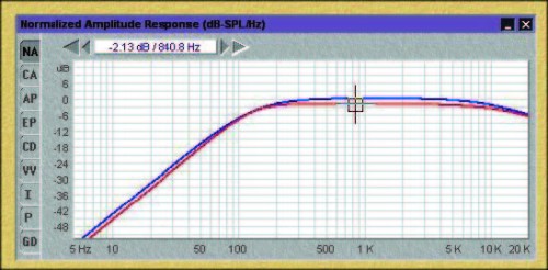
Figure 8. Two traces from a BassBox Pro simulation. Blue is for Rg = 0 ohms and Red is for Rg = 2 ohms and the scale is relative magnitude.
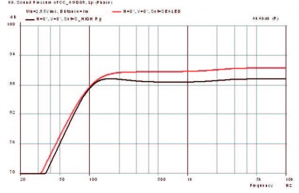
Figure 9. Same two traces as computed by AkAbak. Red is for Rg = 0 ohms, and black is for Rg = 2 ohms. The scale is dB SPL at one meter for 2.83v input. For both modeling programs, the useful low frequency cutoff is close to 100Hz.
.
Figure 8 shows the BassBox SPL prediction for both the Rg = 0 and Rg = 2 ohm condition. The loss for adding the two ohms is 2.15 dB at mid-and the Q, obviously, has increased. The equations predict a 2.2 dB difference. I’m happy with that!
Of course we do not know the exact algorithms used by either program, but for all practical purposes they are in reasonable agreement. AkAbak does use a real cone shape to the driver as compared to a flat piston equivalent used in the equations. BassBox Pro automatically reduces the ‘working’ volume of the enclosure by the volume of the magnet structure.
Table 1 compares the calculations thus far.
Additional box damping, Rab, is not required because the Q is already within range. This is a case where adding electrical resistance inside the box might be considered useful if one is playing “specmanship”. Audible difference? Maybe not.
It will be necessary to build a loudspeaker to check these data. I suspect that with any given production run the mechanical variation may be of the order of some of these differences. It is difficult to control the nature of a spring made of “soft goods”, like the spider and surround (See “Reality Check,” this issue). I found an example of claims made in a spider patent, in case you think it’s simple!
What have we learned? Calculated and modeled predictions are just tools–and they don’t always agree with each other. We are not privy to the internal workings of prediction software, but BassBox is likely to be using piston-equivalent radiation whereas AkAbak uses first-principal acoustic calculation (surface integral) to model a cone shape and also include box internal standing wave resonances (not shown).
Real-world performance will almost never be exactly as predicted when looking at fine detail. However, they are guides for starting a new design. Predicting the performance of a complex system with many variables is always fraught with problems because it becomes impractical to include all of them. Each prediction method tosses out “meaningless” quantities that skew their results away from the other guy (with all good intentions, of course).
Sometimes adding internal resistance is a way of controlling Q at roll off, provided that the loss of sensitivity and RMS heating of the resistor is not a factor. It becomes rather obvious that this particular driver may not be the best choice in this case where the goal is small size. Working the problem backward is possible, of course, where you tell the driver manufacturer what parameter modifications you require.
In Part 4 we will see if improvements can be made by porting the enclosure. dc


