Anatomy of a Service Call
Pat Brown took an average and simple service call and documented his steps to finding the problem and his solution to the problem.
By Pat BrownThe sound system in the Chapel at a local nursing home had all of the typical problems – distortion, poor gain-before-feedback, and intermittent operation. It’s a relatively simple system, but that alone does not guarantee good performance. I decided to help out since there was no budget to bring in a contractor to troubleshoot and repair the system (plus, my mother-in-law asked me). After completing the repairs I thought the solutions to some of the typical problems might be of interest to our readers.
System Overview
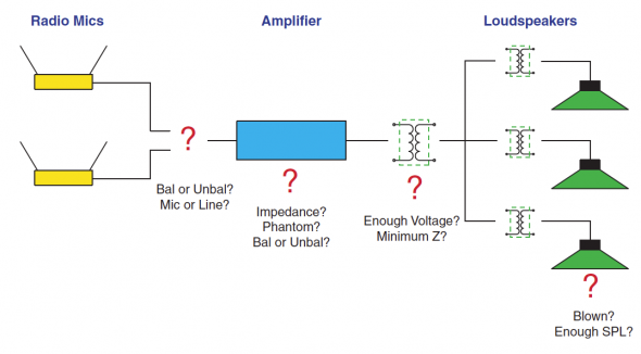
This is a very basic system, so what could go wrong? Two wireless lapel mics drive a small mixer/amplifier, which in turn drives three ceiling loudspeakers via high impedance distribution. There is also a hearing assistance system, which according to the staff has never worked properly.
During a typical chapel service the vocalist holds the wireless lapel mic to sing as though it were a hand-held mic – not ideal but it should still work. The minister uses the other wireless lapel mic in the usual fashion. Both mics distort badly at a fairly low level. They would be much better off with a simple gooseneck mic. It would accommodate both talkers and singers, since both always stand at the lectern. On the other hand there are no installed mic jacks in the room, and the owners do not want visible cables. I elected to keep it simple and just re-implement the existing mics.
Tools of the Trade
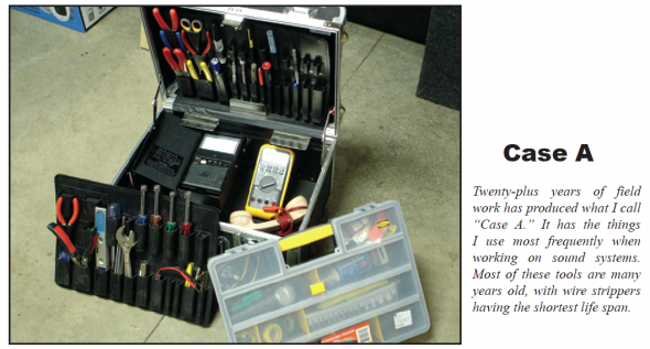
I have two equipment cases. The first is typical toolbox full of hand tools and a few basic meters including a Music Supply TS-1 hand set, a Fluke volt-ohmmeter, Neutrik Minirator and a TOA ZM-104 impedance meter. I refer to this as my “nothing to boot or recharge” case. We’ll call it Case A. The second contains the more sophisticated instruments, including a scope meter, USB audio interface, measurement mic and an Audio Toolbox. You guessed it – Case B. I always start with Case A, and then call in Case B if needed, since it requires a second trip to the truck and a battery check before leaving the shop. Fortunately, this whole project could be handled with Case A.
Divide and Conquer
Since just about any stage of this system (or several) could be the culprit, I elected to start at the input and work through to the output, correcting and optimizing things as I went. First in the chain are the wireless mics.
Ambiguous Outputs
Since the mics sound distorted, the first step is to find out if they are working properly. These are entry level units that use a 1/4-inch jack for signal output. The first question was “Is this output balanced or unbalanced?” The slow insertion of a Tip-Ring-Sleeve plug into the output jack revealed that it has three electrical contacts, so it is potentially a balanced output. A quick listen with the TS-1 handset across a TRS plug revealed that there was only signal on the tip. This test also revealed that the signal level was close to line level, since a mic level signal would not be audible on the passive handset. Since it could still be balanced with the ring grounded through a resistor, I used the TOA ZM-104 to check the impedance from T and R to S. The ring-to-sleeve connection is a dead short, so this is an unbalanced output and should be treated as though it is a simple TS output jack.
The mics sounded okay through the TS-1, so for now I ruled them out as the source of the distortion and proceeded to interface them with the mixer/amplifier.
A Mixer / Amplifier Upgrade
The amplifier in the rack was inadequate for the application. There is only one input channel, and the installer had “Y’d” both wireless mics into it. The output power was too low, and it lacked the proper outputs to drive the auxiliary systems in the facility. I found a unit in the shop to provide as a substitute. It has two balanced mic level inputs, plus an aux bus and line out. There is no provision for driving a high impedance loudspeaker system, but one can always add a transformer to get that. I decided to go with it.
Now, interfacing the wireless mics to the mixer/ amplifier would seem pretty straight forward – but wait a minute. The inputs are labeled “Low-Z” – not likely in a modern mic input. A quick check with the ZM-104 showed the input impedance to be about 8k ohms – a fairly high value for a mic input, and fortunately high enough to not load the wireless receivers.
The impedance is appropriate, but how about the level? The TS-1 revealed that the receiver outputs are pretty hot, probably too hot for a mic level input. Also, the inputs on the mixer/amplifier are balanced XL, which opens the possibility of the presence of phantom power. A line level unbalanced output to a mic level input with the potential of phantom power? It’s not looking good.
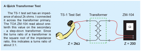
Since it is not a good idea to send phantom power to an entry level unbalanced receiver, I thought that I had better check. The TS-1 delivered a significant “click” when connected between pin 1 and each of the other pins on the mixer’s input XL connector. This indicates the presence of DC. A quick test with a volt-ohmmeter revealed 24VDC phantom power (with no labeling on the input to indicate its presence). I determined that the inputs were mic level by using the handset as a mic by connecting it across pins 2 and 3. A simple “Check 1,2” produced plenty of level, so the input had to be mic level. This was not going to be a simple “adapt-the-jack” interface job, but it is a made-to-order situation for a transformer. I had a couple of small ones in the shop that I hoped would work. What I really needed was a “step-down” transformer to drop the output voltage of the receiver and block the phantom power from reaching it. The units that I had were labeled as being “bridging” transformers, which leaves room for doubt regarding what they are actually doing. After all, a 1:1 transformer would present a high (bridging) impedance to an output if its secondary is connected to a high impedance input. There’s no need to guess, since the tools in Case A could quickly determine the turns ratio of these units. See the sidebar below for the method that I used. The 3:1 transformer turns ratio would be adequate for dropping the receiver output voltage to drive the mic level inputs. I installed the transformers and set the mixer input levels to their mid (12 o’clock) setting. A quick listen with the handset at the mixer/amplifier’s output revealed that things were loud and clear.
On to the Output
It was now time to address how to drive the ceiling loudspeakers. A test of the loudspeaker line with the ZM-104 impedance meter revealed that all loudspeakers were operating and that the total impedance was about 2500 ohms. The 1kHz square wave was clearly audible from all of them. Since voice coil impedance is typically about 8 ohms nominal, and three in parallel would be lower yet, there had to be step-down transformers on the loudspeakers. These make the loudspeaker’s voice coil impedance appear as a much higher impedance to the amplifier This immediately suggests the need for a high voltage amplifier output. The new amplifier is rated at 100 watts into 8 ohms, which tells me that its output voltage should be around 30Vrms for a sine wave (and about 1/3 of this voltage for program). This is possibly too low to drive a high voltage distribution system. On the other hand, this place doesn’t need a lot of level so it might just be adequate. Rather than order in a step-up transformer (or root around for one in the “bone yard”) I decided to just try it and see how well it worked. I maxed-out the wall mount attenuator in the chapel and slowly increased the output level control on the amplifier while talking through one of the wireless mics. I was delighted to find that I could get adequate level out of the system with the available voltage, even though I had to turn it nearly all of the way up. The installer had tapped the loudspeakers too high. The correct tap setting would be the one that produced the needed SPL at a higher amplifier output voltage (about 30Vrms program for a 70.7 volt system). Speaking loudly caused occasional flashing of the limit light which actually turned out to be a good thing. Since the amplifier limits rather than clips, the limit circuit could be used to prevent excess sound level if someone eats the mic – an all-to-common occurrence when you have people singing into lapel mics. So in this case it ended up that driving a high impedance loudspeaker system from an amplifier without a high voltage output was better than stepping up to a higher voltage. You never know until you try, and trying is usually free.
This is not a recommended practice for a new design, especially one that might be expanded later. I always try to get a pretty high voltage (20-30Vrms) on 70.7 volt lines and then tap it back at the loudspeaker to whatever is needed. In this case, re-tapping the loudspeakers would be an ordeal, and there was no need to add any others to the system. I elected to break the rules and drive the loudspeaker system without a step-up transformer.
Wrapping it Up
I drove the balanced input of the hearing assist system from the unbalanced auxiliary mixer output using the forward-referenced wiring scheme (www.jensen-transformers. com). In the old system it was driven from the high voltage amplifier output, but its input was not configured to handle the high voltage. The severe distortion had kept them from ever using the system. It now works fine and is in regular use.
Wireless Mic Reception
I walked the chapel with both wireless mics to check their reception. One worked fine everywhere in the room. The other had a few drop-outs. Rule number one is to make sure that the transmitter “sees” the receiver. Both receivers were in a closet (of course) in an adjacent room – not good. The entry level units do not have detachable antennae, so there was no way to remote them into the room. The receivers themselves could (should) be placed in the chapel, but this means additional wiring and the security problem of having visible equipment. The short term solution is to leave the closet door open during the use of the system – simple but adequate for now. I’m completely certain that they will forget to open the door after a week or two and will have drop-outs again. We can fix it right later if other options materialize. Anyway, I’m still hopeful that they will eventually do away with the wireless mics and install a lectern mic.
Conclusion
This case study illustrates some of the common situations that sound technicians face in the field, especially with entry-level gear. These included:
- 1. Consumer-level unbalanced outputs with ambiguous connector topology (and no labels other than “Output”)
- 2. Phantom-powered inputs with no labeling other than “Low-Z”
- 3. Low impedance line level sources Y’d with other ones and driving a mic level input (with phantom power)
- 4. Transformers with no labeled turns ratio
- 5. Improperly tapped ceiling loudspeakers
All of these things were easily addressed with the simple tools that live in my tool case – a hand set, an impedance meter, a VOM and some adapters. The system sounds good, has no audible noise and low distortion. It’s not fancy but after the revisions it is adequate for the application. This is a good time to note that all of these problems could have been avoided by using professional gear to start with, especially balanced output wireless mics with a mic/line switch and detachable antennae along with a decent mixer/amplifier.
This system was probably the low bid. Consumers will always be uninformed regarding the difference between pro and consumer gear, so systems like this one will keep being specified and installed. This represents job security for audio professionals, who can step in on the inevitable upgrades that such systems require. pb


